
The science behind amine column corrosion and remedial solutions
C. BATEMAN, Integrated Global Services, Nottingham, England, UK
Corrosion in ammonia plants—specifically in amine columns—can be a significant concern due to the harsh operating conditions and corrosive nature of the chemicals involved. Amine columns are an essential component of gas processing units, often used for removing acidic gases like carbon dioxide (CO2) and hydrogen sulfide (H2S) from hydrocarbon streams. The most common amine used for this purpose is monoethanolamine (MEA).
This article examines how and why corrosion takes place within amine columns and the corrosion mitigation strategies available.
Amine column corrosion mechanisms. To understand the solution to the problem, it is important to first understand the science behind the problem of corrosion—in this case, the amine column corrosion mechanisms. In the amine system, most of the corrosion is related to acid gas breakout and the subsequent attack on the metal surface, usually at elevated temperatures. Since corrosion is a chemical reaction, high temperatures always accelerate corrosion activity because reactions occur faster and more aggressively at higher temperatures.
Often, several factors contribute to failure by corrosion. Statistics show that nearly 50% of corrosion incidents occur in areas exposed to high temperatures, making organic coatings often ineffective. In ammonia plants, most corrosion is related to H2S or CO2 breakout and the subsequent attack on the metal surfaces, usually in areas of elevated temperature or high pressure drop (leading to condensation).
More potential corrosion mechanisms exist in amine columns (FIG. 1). Corrosion can occur in the upper sections of the amine column, especially if there is a significant amount of CO2 and H2S in the gas feed. These gases can react with moisture in the system to form acidic compounds, which can lead to corrosion of the column's internal surfaces.
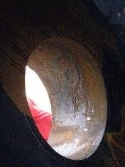
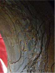
FIG. 1. Corrosion on the manway of an amine column.
Several solutions are available to treat the issue of corrosion. While the damage cannot be reversed, if repaired using the correct technique and application, the lifespan and performance of the equipment can be significantly increased.
Corrosion mitigation strategies in amine columns. Many amine columns have the upper area cladded with 316 stainless steel as part of the original design. Process control and changes to the feed typically mean that the amine column will experience corrosion in other areas, often directly below the clad section. The nature and form of the corrosion mechanism often manifest themselves as a localized pitting attack with high corrosion rates. That can quickly remove the corrosion allowance and damage the integrity of the unit, requiring intervention and mechanical repair to rebuild the pressure boundary.
Aside from operational considerations, several mitigation or repair strategies have historically been employed when internal metal loss occurs.
Welding and panel replacement. Some mechanical options include the installation of temporary clamps and plugs, column section replacement and the application of an internal weld overlay. The time required for these, as well as the post-weld heat treatment (PWHT) required to remove heat-affected zones (HAZs) and structural support considerations, often demand extended turnaround or shutdown schedules and associated production losses.
Organic coatings. Temperature and chemical compatibility limitations have prevented the effective use of organic coatings in this environment. Organic coatings are at times used to mitigate corrosion in process vessels operating at lower temperatures and can be effective, however, organic coatings are limited to immersion temperatures below 120°C, depending on the chosen coating system.
Organic coatings are also inherently more susceptible to mechanical damage and do not withstand cleaning/steam-out processes. Organic coatings are intolerant to application variations such as surface contamination (e.g. salt), insufficient grit blasting profile, ambient and surface temperatures, all of which can lead to premature failure.
Thermal spray. Thermal spray technology has been utilized for the application of corrosion-resistant alloys (CRAs) since the 1980s, spraying metals widely used in the welding process. However, it was quickly noted that the thermal spray process can negatively affect the condition of the material being sprayed. The resulting cladding—when using traditional metal alloys and commercially available thermal spray equipment—was permeable.
This permeability, coupled with internal stress and a lower bond strength with the base metal, created a path for corrosion and premature failure. These early failures resulted in an understandable and rather universal distrust of early iterations of commercially available thermal spray technology. At the same time, this evoked a thought-provoking question: Is it possible to eliminate the permeability, porosity and internal stress of the applied thermal spray cladding and improve bond strength?
Thermal spray evolution: High-velocity thermal spray (HVTS) alloy cladding. Engineers and material scientists have successfully developed a solution to this problem by redesigning both the equipment used to apply the metal cladding, the process technology, and the alloy of the feedstock material.
Material. The thermal spray application process is aggressive from a thermal and kinetic perspective. It is expected that detrimental material segregation or degradation can occur to the selected alloy during the thermal spray application.
This makes unmodified wrought alloys—such as an unmodified Hastelloy C-276 material—unsuitable for application by means of a thermal spray process. Several mitigating technologies are applied by the author’s company to prevent this. These include alloy composition modification and procedural control to achieve an effective uncompromised barrier.
True high velocity. The atomization velocity is a critical success factor in thermal spray cladding for critical equipment operating in corrosive liquid and gas environments. For thermal spray cladding applied with a wire feedstock, a high-velocity process is defined where the material atomization occurs in a super-sonic gas stream (gas stream velocity equal to or greater than Mach 1), which results in specific particle characteristics critical to achieving an impermeable barrier.
Creating impermeable protection. As particles are ejected from the thermal spray torch at a high temperature and velocity, they are exposed to air with a high nitrogen and oxygen content. The molten particles are inclined to rapidly oxidize in flight. On deposition, oxide bands are formed in layers along with the metal splats.
These oxide structures constitute permeable pathways through the applied thermal spray and are to be avoided in any application, especially where corrosion is present. Chemical and process controls are employed by the author’s company to significantly inhibit in-flight oxide formation.
Bond strength. The challenge of bond strength, between both the applied metal particles and the substrate, was solved by increasing the velocity and improving the quality of the substrate surface preparation. When the molten metal particles hit the substrate with a suitable profile at speeds close to supersonic, they embed the metal into the substrate forming tight bonds. The particles do not have a perfectly smooth microstructure; this feature promotes good intersplat adhesion. Multiple additional overlapping passes of the thermal spray torch then create a 500-micron thick cladding with excellent adhesion throughout. American Society for Testing and Materials (ASTM) adhesion pull-off tests typically measure bond strengths in excess of 60 MPa.
CASE STUDY: SEVERE AMINE COLUMN CORROSION PERMANENTLY FROZEN
During a scheduled shutdown inspection, a worrying discovery was made inside an MDEA amine regeneration column on the natural gas liquid (NGL) train at a plant in Asia. The internal surfaces of the lower section of the column, fabricated from carbon steel, had suffered severe localized corrosion.
A significant wall thickness reduction was found beneath the trays. Pitting was identified up to 2.3 mm in depth.
The root cause of this unexpected pitting corrosion was found to be tube failure in an associated upstream reboiler, which had led to the severe localized acid gas attack of the column shell in the area where the reboiler feed entered via an inlet nozzle.
If left untreated, this would eventually lead to failure which could potentially cost the plant millions of dollars to replace the column. In addition, due to the nature of the sour feed, loss of containment poses major safety and environmental risks.
Fitness-for-service (FFS) engineering analysis. A third-party engineering company carried out a full FFS engineering analysis of the column in its current corroded state (FIG. 2). Based on the reduced shell thickness corrosion mapping report, the amine regeneration column passed the load combinations and the results proved to be within the allowable membrane stress limits. The calculated buckling factors were also above the minimum allowable limit.
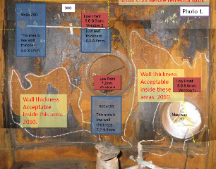
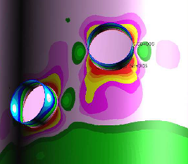
FIG. 2. Corrosion mapping (left) and FFS engineering analysis (right).
Now that the asset owner had ascertained that the amine column was fit for use in its current condition, they had to ensure that no further metal loss occurred to the column shell pressure boundary. The current amine corrosion condition needed to be resolved.
The chosen solution. The plant chose to use an HVTS alloy cladding solution to fix the issue of corrosion in its amine column (FIG. 3). This solution provided the same benefits as a high-nobility weld overlay corrosion barrier, with several additional advantages—including a rapid application speed—without creating HAZ, requiring PWHT or distorting the base material.

FIG. 3. HVTS application.
The inspection. Following the application, the amine regeneration column was closely monitored and inspected both externally and internally to demonstrate that the remaining shell pressure boundary was maintained (FIG. 4). After two years the wall thickness had not changed so the asset owner subsequently cancelled the order for the new column and continued operation.
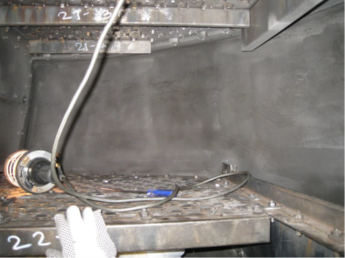
FIG. 4. View of the amine column during final inspection.
The application saved the asset owner both the combined capital expense to replace or structurally strengthen the amine column and the associated operating expense of an extended unplanned shutdown that would have been required to carry out the installation and commissioning of a new one.
In addition, it enabled the NGL plant to subsequently engineer, procure and commission two new columns adjacent to the existing one and tie these in with minimum interruption to production. In total, these combined savings thanks to taking amine corrosion under control, amounted to approximately $40 MM for the plant.


Comments