
Shutdown and startup of an amine system
J. A. STAVROS and J. N. TAYLOR, Phillips 66 Bayway Refinery, Linden, New Jersey
A smooth startup of an amine system begins with properly taking the system out of service. It is important to circulate amine while maintaining adequate steam to the amine regenerator so the entire inventory of amine solution has been stripped of hydrogen sulfide (H2S) and carbon dioxide (CO2). This prevents safety concerns with the shipping and handling of the amine solution and makes the solution less corrosive to carbon-steel process and storage vessels. A simple step to check the lean amine loading before turning off the steam to the regenerator is advised. An alternative to the lean loading check is to dip lead acetate paper into the amine solution. The amine is adequately stripped if the lead acetate paper remains white-to-very light brown after contacting the amine solution. Particulate filters should remain in service during the shutdown. Reducing the micron (µm) size of particulate filters, down to 10 µm if possible, during shutdown is recommended to thoroughly clean the system.
There is no reason for excessively long stripping, which is the same as putting the amine system in hot standby. A rule of thumb is to circulate for three to five turnovers of the system volume. As all the H2S is stripped from the amine, iron sulfide from the protective iron sulfide layer protecting the piping and equipment will go back into the solution due to solution equilibrium. When the iron sulfide is back in the solution, the previously clear amine turns brown in hot standby (FIG. 1). As more iron sulfide enters the solution, the likelihood of filter plugging and future leaks from disturbing the protective iron sulfide layer increases. If an amine system has particularly high heat stable salts, the protective iron sulfide layer will be dissolved at a higher rate, which should be considered when establishing shutdown procedures.
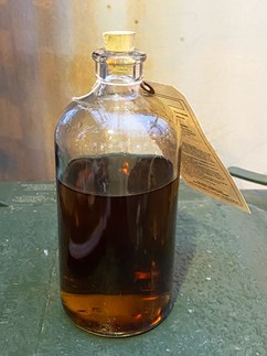
FIG. 1. Amine solution turns brown after 12 hr of stripping for shutdown purposes.
All contactors and liquid/liquid (L/L) treaters should be pumped out during shutdown, removing all liquid. Amines and hydrocarbons left in vessels that are not opened during a turnaround will act as contaminants that can cause foaming or create iron sulfide particulates during the startup.
Storing amine. The Amine Best Practices Group (ABPG) advises that lean amine should not be stored in process vessels for more than 4 wk–6 wk. One reason for this is that lean amine is mildly corrosive when sitting stagnant in steel process vessels. In addition, iron sulfide particles grow and drop out of the solution when the amine solution sits stagnant and cold. Lean amine solution that is sent to temporary storage tanks should preferably be blanketed with nitrogen to prevent corrosion and, to a lesser extent, amine degradation. The authors recommend that temporary storage containers be made of austenitic stainless steel if cracking is a concern at ambient temperatures. Methyldiethanolamine (MDEA) and diethanolamine (DEA) solutions must be blanketed with nitrogen to prevent the oxygen-assisted degradation of MDEA and DEA to bicine, a chelating agent that dissolves the protective iron sulfide layer that has been established in existing amine systems.
The ABPG is aware of at least one case where uninsulated hot steam tracing was touching a carbon-steel amine regenerator used to store amine solution for a period of years. A leak occurred that was attributed to both external corrosion due to the resulting hot spot from the steam tracing and internal corrosion due to the lean amine H2S loading. The operator must consider the risk of storing lean amine in a process vessel where bare steam tracing is applied.
Vacuum trucks. Vacuum trucks used to transport lean amine to and from storage vessels must be cleaned before use in amine systems. Vacuum trucks are a source of contamination and have contributed unwanted caustic, hydrocarbons, soaps and surfactants to refinery amine systems.
Cleaning the amine system. Cleaning fluids and chemicals that are not properly rinsed from amine system vessels can produce horrible foaming. A well-known H2S scavenger used for chemical cleaning—if left in an amine system—will result in amine foaming at a concentration of only 10 ppmw. Recently, a refiner found manganese sulfide particulates in a tail gas amine system that foamed weeks after startup. The manganese sulfide was attributed to residual potassium permanganate (a H2S scavenger) used for amine system cleaning.
Note: The most important thing to remember from this document is that every elbow, fitting, tray downcomer and small space must be rinsed to thoroughly remove any cleaning fluids used to prepare equipment for personnel entry. Cleaning fluids are normally surfactants, and even 10 ppmw contamination can result in severe prolonged foaming.
Preparing the vessel for chemical cleaning. The U.S. Environmental Protection Agency’s (EPA’s) “Petroleum Refinery Sector Rule (Risk and Technology Review and New Source Performance Standards)” states that a vessel should have < 10% lower explosive limit (LEL) before the vessel is opened.1 If a site is using close-coupled wash connections (as shown in FIG. 2), the authors’ experience has shown that it may take a long time (days) to remove H2S and the LEL to acceptable levels before the wash connection can be installed to begin chemical cleaning.
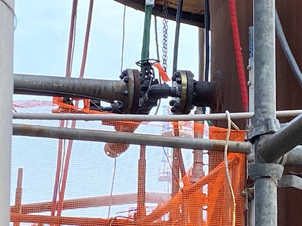
FIG. 2. A close-coupled wash connection (no valve on the vessel nozzle).
A simple fix to shorten the time required to install wash connections for chemical cleaning is to install double block and bleeds (FIG. 3) where all wash connections are required. With the double block and bleed, only a short section of piping needs to be free of H2S and LEL rather than an entire vessel, which might be filled with sludge and pyrophoric material.
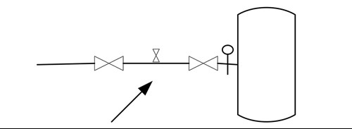
FIG. 3. Insert a wash connection between the block valves.
Considerations when decontaminating amine systems using chemical cleaning technologies. Numerous vendors offer different chemical cleaning technologies. The ABPG has had positive experiences with almost every vendor and chemical cleaning package. Some chemical cleaning procedures use low-strength acids with surfactants, others use low-strength caustic (sodium hydroxide) with surfactants, and some cleaning procedures use surfactant packages only. Chemical cleanings in amine systems are completed using both vapor phase and liquid phase cleaning. The authors have historically had much better results with liquid phase cleaning procedures on vessels in amine service. Liquid cleaning procedures should include a step to move liquid upward in the vessel to remove materials that float on top of the liquid.
An important consideration when choosing a chemical cleaning package is the materials of construction of the pressure vessels to be cleaned. Stainless-steel vessels, whether solid stainless or clad with stainless, require low-chloride water to prevent stress chloride cracking. Stainless steel is much more sensitive to chloride cracking as amine is removed from the equipment, as the pH of the liquid in the tower decreases and oxygen is introduced. Some chemical cleaning procedures work better when the temperature is increased, so steam is used to heat the liquid in the pressure vessel. The likelihood of chloride cracking also increases with increasing temperature and decreasing pH. At least one refining company specifies chloride concentrations of < 5 ppmw prior to introducing acid or steaming procedures, as the steaming of systems can result in chloride concentration. Because the risk of chloride cracking increases with decreasing pH and increasing temperature, the ABPG recommends demineralized water (zero chlorides) for both initial and final washes when chemical cleaning stainless-steel equipment in amine service.
Carbon-steel vessels in amine service should be post-weld heat treated (PWHT) to prevent cracking. Unfortunately, some refiners have found that not all of their pressure vessels—and especially piping in amine service—have been PWHT. For this reason, the ABPG recommends steam-out procedures should be avoided in systems with non-PWHT carbon steels.
A typical caustic-based cleaning procedure used by refiners is:
- Flush equipment with demineralized water, with a maximum temperature of 140°F
- Circulate a solution of 10 wt% caustic and surfactant-containing chemicals, with a maximum temperature of 140°F
- Flush tower with demineralized water.
A typical acid-based cleaning procedure used by refiners is:
- Flush with demineralized water to remove bulk amine to very low amine concentration (this step will also remove chlorides, as needed)
- Circulate H2S scavenger to remove H2S
- Circulate low-strength acid (< 10 wt%)—the authors’ company has seen sulfamic, sulfuric and citric acid used for this step; H2S scavenger can been added during this step in addition to Step #2
- Flush system with demineralized water to raise pH
- Neutralize system with low-strength (< 5 wt%) soda ash
- Flush system with demineralized water until pH rises to neutral or greater.
An advantage of using a caustic cleaning procedure is that the procedure is fast, as no neutralization steps are required. Also, caustic reacts with H2S—it is a stronger base than amine and helps to prevent accidental H2S releases during the chemical cleaning process. A disadvantage of using caustic for chemical cleaning is that temperatures should be limited to no more than 140°F or the likelihood of cracking is high on non-PWHT steel. While most refiners use only PWHT steel in amine service, the authors have found that cracking on welds has occurred on legacy equipment that was never heat treated. Chemical cleaning with caustic requires more skill on the part of the chemical cleaning vendor.
Acids can be easier to work with than caustic because caustic-induced cracking is eliminated. However, carbon-steel vessels must be neutralized after acid cleaning, adding more steps and time to the chemical cleaning procedure. Acid cleaning also removes the protective iron sulfide layer present on carbon-steel equipment in amine service. Consequently, the amine solution will corrode carbon-steel equipment again on startup, usually resulting in an excess of iron sulfide particles in the solution, which increases the chances of foaming after startup. Operators should expect filter plugging and the need for frequent filter changes during startup after acid cleaning has been utilized.
FIG. 4 shows extensive debris in an amine regenerator after a vapor phase cleaning using surfactants only. The debris is mostly iron sulfide (70 wt%) and iron oxide. While the regenerator was free of H2S and LEL after the vapor phase cleaning, it took days to vacuum all the debris off the trays, negating any cost and time advantages gained by this comparatively less-expensive procedure.
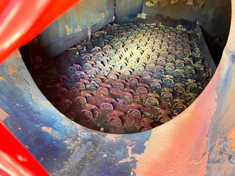
FIG. 4. An amine regenerator tray after a failed chemical cleaning.
The authors have no preference for which type of chemical cleaning is used, provided all surfactant chemicals are rinsed from the system to prevent amine foaming. It is vital to carefully check references for all chemical cleaning vendors.
New equipment or old equipment with new internals. New pressure vessels and new vessel internals (e.g., trays, random packing, structured packing) are often delivered with residual machining oils and surfactants. These materials can produce foaming in new equipment.2 To remove machining oils, it is recommended to rinse new pressure vessels, piping and vessels with new internals with an alkaline solution of 3 wt%–10 wt% NaOH (caustic). Alkaline solutions of trisodium phosphate or 2 wt%–5 wt% soda ash have also been used successfully to remove oil and surfactants. When using caustic, temperatures must be kept < 140°F to prevent alkaline stress corrosion cracking (SCC) if materials are susceptible to SCC.
Heating caustic solutions in reboilers or thermal reclaimers prior to use in other equipment is not recommended as it is easy to overheat the caustic solution. Water washing is not guaranteed to remove machining oils—the alkalinity of the solution is important. Some amine vendors recommend washing new equipment with low-strength amine before startup. A good water wash should be performed after the caustic cleaning to remove caustic and prevent sodium accumulation in the amine solution. Target neutral pH to end the water wash. New internals can also be cleaned before installation in pressure vessels, which may be easier than internal cleaning.
Amine import. When purchasing new amine for a startup, grab a sample of the amine from each fresh amine truck, if possible, as trucks can be contaminated.
Startup. Use the same brand and type of amine particulate filter used before shutdown. Use the same brand and type of activated charcoal used before shutdown. If the amine system was stable and without foam before shutdown, do not make changes. Certain types of particulate filters and activated charcoals are incompatible with amine systems. Changing these materials just adds more items to disqualify from a root cause analysis of an event after startup. Local vendors may be unaware that some items they are selling are incompatible with amine solutions.
Filter coalescers used immediately upstream of gas contactors should be changed out during the turnaround or maintenance period. Use the same brand and type of coalescer used before shutdown for the same reasons listed above for filters and activated charcoal.
Avoid loading activated carbon into an empty vessel. Fill the carbon filter vessel about 1/3 full of water before adding carbon. After loading, fill the vessel with water in an upflow direction until water comes out the top to displace any air. Allow water to flow to 2–3 bed volumes to remove fines near the top of the vessel. Reverse the water flow for 2–3 bed volumes to remove the carbon fines near the bottom of the bed. Allow at least 12 hr to wet the carbon and displace the air in the carbon pores.
Normal operating amine strength should be established as quickly as possible, preferably before starting amine circulation. The easiest way to do this is to fill the lean amine surge tank, rich amine surge tank or even a temporary Baker tank with enough fresh amine (usually 79 wt%–100 wt% amine) so that just by adding condensate to the mixing vessel amine, an appropriate amine operating strength (wt%) is achievable. Carbon steel is an acceptable material for fresh amine.
Amine solution has a specific gravity close to 1. The lean amine surge drum, rich amine surge drum and amine reflux accumulator operate at moderate temperatures and, consequently, the operating specific gravity is not much different from ambient startup conditions. Calibrate level instruments when there is enough amine solution in them and before the amine solution is sent to any gas or liquid contactors. Pressure up these vessels to operating pressure as differential pressure instruments can be sensitive to operating pressure. A second calibration may be necessary on the amine regenerator that operates at 250°F or higher, resulting in lower amine solution specific gravity.
Ensure that operations and technical support know how level instruments are supposed to work in each process vessel. Ensure that alarms are active in the distributed control system (DCS) for all instruments. Alarms may have been deactivated during a shutdown period. Any level instrument reading > 80% level may really be over the top of the level instrument’s range. Also, be wary of level instruments that “flatline.” A level instrument with no fluctuations in level is often indicative of a high level over the level instrument’s range and not of a stable liquid level. A common startup error begins by first allowing a high level in the amine regenerator bottoms that floods the reboiler with cold liquid. Steam flow is then added to the reboiler to help reduce the liquid level in the tower bottoms. If the steam is added too quickly, large bubbles can form that quickly rise in the tower, resulting in catastrophic tray and/or packing damage (FIG. 5), and random packing can be lifted out of the tower and into the overhead piping and reflux accumulator.
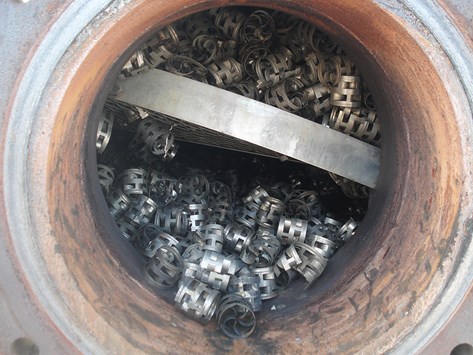
FIG. 5. A displaced packing support grid after a high liquid level in the reboiler.
Attempting to rapidly adjust the concentration after sour hydrocarbon gases and liquid have been added to the system should be avoided. The ABPG has experience with foaming events associated with changing amine concentrations rapidly. Foaming has been associated with both increasing and decreasing amine concentrations rapidly. Increasing amine concentration rapidly by adding 100 wt% fresh amine will most often turn amine black, as iron sulfide particles are formed with increasing pH. Iron sulfide particles can stabilize foam.
Check the amine concentration in storage vessels—it should be within a few wt% of operating strength. Adjust this in storage vessels, if necessary. Begin adding the amine solution to process vessels after air is removed from the vessels to address both flammability and amine degradation concerns.
Have nitrogen connected to the amine regenerator. The nitrogen will make it easier to maintain stable pressure control before the amine absorbs acid gases—it will also prevent pulling a vacuum in the regenerator if steam is lost before acid gases are present. Using nitrogen is often necessary to maintain enough pressure so the lean amine pumps will work [enough net positive suction head (NPSH)] or to pressure to the lean amine surge tank if the system does not have a rich amine pump.
Begin by slowly heating the amine regenerator. Check the steam traps on the reboiler for functionality. The goal is to have a hot regenerator before sending any hydrocarbon to the amine contactors and liquid treaters. Heat in the regenerator will lift small amounts of entrained and absorbed hydrocarbons to the regenerator overhead where they can be purged either as liquid from the reflux accumulator or as gas to flare or the sulfur plant (if they are small amounts of hydrocarbon).
Begin circulating the amine solution through the amine contactors and liquid treaters. Take the opportunity to calibrate flowmeters and level instruments on all process vessels.
When the amine solution has been circulating through all process equipment and the amine regenerator overhead temperature is hot enough to produce reflux, begin adding hydrocarbons to the selected amine contactors. Hydrocarbons should come from fractionators that are reasonably close to on-specification. Hydrocarbons that are much heavier than normal entering the amine system and condensing into the amine system are undesirable. Amine can be warmer than normal at this time. H2S removal from the hydrocarbons might suffer but this is acceptable in the short term. Very cold amine condensing a heavy load of hydrocarbons coming from a fractionator that is nowhere near on-specification is undesirable—this will send heavy hydrocarbons, likely gasoline, into the amine system, where is it likely to cause foaming and fool level instruments. The hydrocarbons will then potentially overpressure the amine regenerators and create the potential for loss of H2S containment at the sulfur plant.
Deploy additional staffing to monitor particulate and charcoal filters for plugging. It is likely the filters will plug no matter what precautions are taken to prevent amine system contamination. Change particulate filters as necessary and consider preemptive filter changes. Consider using larger than normal micron sizes at startup, up to 70 µm, because smaller µm-size filters may plug too frequently for personnel to keep up with filter changes. However, remember to reduce to smaller µm-size filters as amine unit operations stabilize. Changing filters frequently to keep the amine free of particulates will significantly reduce the likelihood of foaming and amine carryover events.
When a reasonable flow of acid gas has been established, remember to remove nitrogen from the amine regenerator. It may take a day or two before the control room operator is confident enough to remove the nitrogen. Do not worry about the nitrogen costs. Keeping pressure on the regenerator to avoid level measurement errors will minimize the severity of upsets.
LITERATURE CITED
1 U.S. Environmental Protection Agency (EPA), “Petroleum refinery sector rule: Risk and technology review and new source performance standards—40 CFR.63.643 Miscellaneous process vent provisions,” July 1999.
2 Copper, S., B. Viceral, K. Thomas, S. Goff, J. Contreras, L. Nyadong, J. Stavros and N. Hatcher, “Investigation and diagnosis of startup foaming issues at a new tail gas treater,” Hydrocarbon Processing, April 2022.
ABOUT THE AUTHORS
JASON STAVROS works as a Lead Process Engineer at the Phillips 66 Bayway Refinery in New Jersey. Since 1991, he has worked within the refining and petrochemicals industries throughout Texas, Louisiana, California and New Jersey. Stavros previously served as the Director of Sulfur Processing for Phillips 66, and earned an MS degree in chemical engineering.
JACK TAYLOR works at the Phillips 66 Bayway Refinery as a Corrosion and Materials Engineer with responsibility for the entire facility. He studied mechanical engineering at NJIT in Newark, New Jersey, and then began his career as an intern at Hess Oil, working in the alternative fuel power group. He later transitioned to the Hess Oil refinery in Port Reading, New Jersey, working in various roles before moving to his current role for Phillips 66. Taylor is a leader in his field at Phillips 66 and has company-wide impact. He is a native of New Jersey and lives with his wife Alexandra, two children and his 1969 Dodge Charger.


Comments