
Optimized high-pressure injection system design
M. A. AL-HARBI and A. ALMOGHRABI, Saudi Aramco, Dhahran, Saudi Arabia; and A. D. AL-AMRI, Saudi Aramco, Jafurah, Saudi Arabia
This article details an optimization opportunity that was taken in a high-pressure injection system after a thorough evaluation. The alternative design proposal was evaluated as a potential solution to address the system’s high-pressure rating and associated risks. The proposal suggested eliminating the 36-in. pipe size injection manifold header and extending the discharge pipes to the facility limit, which reduced pipe, valve and flange sizes. In addition, the proposal suggested implementing several control measures to ensure safe and reliable operation, including load-sharing and balancing controllers, anti-surge control loops and overpressure protection instruments.
After evaluating the alternative proposal, it was concluded that de-rating the injection system from a 10,000# rating to a 2,500# rating and modifying the control measures would be the best solution for the project to ensure efficient operation. This would involve purchasing lower-rated materials, modifying the design to accommodate lower ratings and implementing various control measures to ensure a smooth operation. In addition, overpressure protection means were suggested to prevent a dangerous pressure buildup in the system.
Overview of the HUGRS initiative. The Hawiyah Unayzah Gas Reservoir Storage (HUGRS) project is a groundbreaking initiative in the Kingdom of Saudi Arabia that aims to optimize the use of natural gas during low- and high-demand seasons. It involves storing off-peak surplus sales gas in several depleted wells, with the intention of reproducing the gas back into the Master Gas System (MGS) network during high-demand seasons. In addition, the project aims to recover condensate that will be routed to the downstream stabilizing plant for further processing.
The HUGRS project comprises two facilities: injection and reproduction. The injection facility is designed to compress 1,500 MMft3d of sales gas from the MGS, which will then be stored in dedicated wells via five booster compressor trains followed by five injection compressor trains. During peak season, the stored gas will be reproduced at a rate of 2 Bft3d to meet energy demands in the country. The reproduction facility consists of a slug catcher, a reproduction compressor, a condensate system, a gas dehydration (triethylene glycol) unit and a dewpoint control unit (DPCU) (FIG. 1).
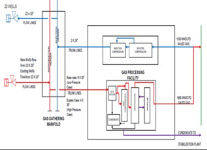
FIG. 1. Schematic of the facility.
The project will operate in a 6-mos cycle, where the sales gas will be injected for 6 mos and then reproduced for the next 6 mos. Both the injection and reproduction facilities share common utility systems, making the project highly efficient and cost effective. This project will significantly impact the country's energy landscape and serve as a model for natural gas optimization worldwide.
Injection facility description. The injection facility (FIG. 2) is a key component of the HUGRS project. It is designed to increase sales gas pressure from 800 psig up to 5,300 psig through five booster and five injection compressor trains. Each booster compressor consists of two stages, with the first stage increasing the pressure from 800 psig to 1,480 psig, and the second stage increasing the pressure to 2,720 psig. The compressed gas is then gathered in a booster manifold and distributed into the five injection compressors, where the pressure is further increased to meet the 5,300-psig requirement. The gas from these five compressors is collected in a 36-in. pipe injection manifold header that travels to the facility’s battery limit and is then sent to the gas gathering manifold (GGM) through two 30-in. trunk lines. In addition, the injection facility has been designed to offer maximum flexibility during the pressurization stage. The facility can bypass the booster trains and use a 36-in. bypass header across the injection trains to divert gas directly to the wells at 2,720-psig pressure during the early injection stage.
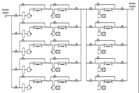
FIG. 2. Layout of the injection facility.
The design pressure of the injection compressor suction was determined based on two scenarios:
- Compressor performance curves. It was assumed that each section was taken to the surge control line—the overall expected ratio was 8:6.
- In the black discharge scenario of the injection compressor, neither the mechanical nor electrical protections were considered for the design pressure selection.
These two factors forced the design pressure to increase to 7,100 psig, and ratings for pipes, valves and flanges were set to the 10,000# rating from the injection discharge section to the launcher and receiver areas. In terms of material availability and system maintenance, several concerns were raised.
High-pressure design system challenges and consequences. The booster and injection compressors, which are the backbone of the injection facility, were designed to operate at high pressures and to handle large volumes of gas flow. However, this high-pressure design posed several challenges and possible consequences that had to be carefully considered and re-evaluated to ensure the safe and efficient operation of the facility.
One of the major challenges of the high-pressure design was securing the necessary material for the injection compressor discharge system, including pipes, flanges, fittings, elbows, field instruments and valves. These components must be rated at 10,000#, which is not a typical material specification in the oil and gas industry. As a result, the market availability and securing such materials posed significant challenges during the accelerated project schedule.
Another challenge was maintenance. The injection compressor discharge pipeline alone requires 344 field instruments that must be rated at 10,000#. Maintaining such a large and heavy pipeline is a significant challenge, requiring specialized skills and equipment.
To address these challenges, an alternative proposal was considered and evaluated thoroughly. This proposal involved reducing the design pressure and the required size of the injection discharge line to make it more manageable and easier to procure and maintain. Also, the proposal involved exploring alternative materials and design specifications that would meet the project requirements while addressing the challenges posed by the high-pressure design.
The project team took proactive steps to address these challenges and develop solutions that would meet the project requirements while mitigating potential risks.
Methodology and study basis. A comprehensive engineering analysis was conducted to rigorously evaluate various design options and identify the most effective design pressure to support the project’s cost and schedule. This in-depth assessment included:
- Considering all operating modes/upsets for the injection facility, including main parameter changes, equipment failures and the primary streams’ boundary conditions.
- Reviewing the system and compressor controls.
- Studying the compressor datasheet and performance curve.
- Assessing the market outlook and the delivery times for materials (such as pipes, valves, flanges, instrumentation)
- Identifying the worst operating mode and reviewing the mitigation measures.
- Conducting three dynamic runs to assess the system’s hydraulic response for the design and upset conditions. These transient simulations included:
- Blocked discharge of the injection compressor and opening of the anti-surge valve, as well as the monitoring time needed to reach the relieving pressure of 6,000 psia, and the relief valves setpoint.
- Blocked discharge of the booster compressor and opening of the anti-surge valve, as well as the monitoring time needed to reach the relieving pressure of 3,050 psia
- The fail-open suction throttle valve on the booster suction of around 900 psig, and the monitor booster/injection compressor performance.
Alternative design. An alternative design was proposed to address the challenges posed by the system’s size and high-pressure rating of 10,000# in the original design.
System’s network size. After conducting a market assessment focused on the procurement of 10,000#-rated components for the injection facility (which encompasses pipes, valves, flanges and instrumentation), it was recommended to downsize these elements to mitigate potential schedule delays. Therefore, a 36-in. injection manifold header was eliminated, and, instead, five discharge pipes were extended to the facility’s battery limit (FIG. 3).
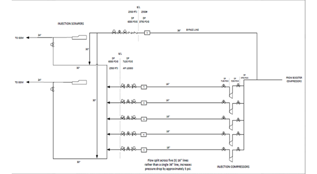
FIG. 3. New network configuration.
This configuration offered benefits, including the elimination of:
- 10,000#-rated valves in the 36-in. bypass line
- 10,000#-rated 36-in. and 30-in. ball valves (the largest 10,000#-rated valve was 16 in.)
- 10,000#-rated 36-in. and 30-in. flanges (the largest 10,000#-rated flange was 16 in.)
- 10,000#-rated 36-in. and 30-in. pipes (the largest 10,000#-rated pipe was 16 in.).
System control modification. Although the new configuration reduced the material sizes and simplified the system’s design, it did not fully address the challenges associated with the high-pressure rating of 10,000#. Therefore, the network controls and safeguards were thoroughly assessed with the objective of lowering the design pressure rating to 2,500# and ensuring safe and reliable operation.
Section 1: Process control modification for the booster and injection compressor. The following were some of the modifications completed on the project:
- Master performance controller: The master performance controller regulates the suction manifold pressure, operating the suction throttling valves via associated load-sharing controllers. This ensures that the suction pressure remains within the desired range.
- Load-sharing and balancing controller: The load-sharing and balancing controller ensures that each compressor is running an equal distance from its surge control line, thus maintaining equal flow distribution (FIG. 4).
- Compressor surge control: The anti-surge control loop modulates an anti-surge valve, which tends to open when the deviation of the operating point is negative. This control system ensures that the compressor operates safely without any surge condition.
- Anti-stone wall controller: During the initial startup phase, pressure at the compressor discharge pipeline is low. A control valve at the compressor discharge is provided to protect the compressor against the stone-wall condition, ensuring safe and reliable operation.
- Motor power limiter: The motor power limiter was implemented in correlation with the suction pressure for each compressor train, thus decreasing the throttling valve opening when the motor power exceeds the limit setpoint. This control system prevents the compressor from overloading, ensuring safe and reliable operation.
- Compressor discharge pressure override: The compressor discharge pressure override was implemented on the anti-surge controllers, increasing the recycle flow when the discharge pressure exceeds the limit setpoint. This control system ensures that the compressor operates safely without any overpressure conditions.
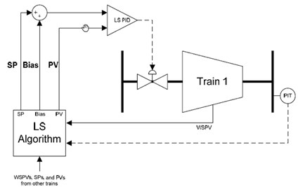
FIG. 4. Compressor load sharing.
Section 2: Overpressure protection for the injection compressor system. The following were some of the modifications to the project’s injection compressor system:
- Compressor discharge pressure limiter: The anti-surge valve and suction throttling valve react to limit the compressor performance in single or load-sharing modes.
- Compressor discharge header pressure limiter: The discharge valve reacts to limit the compressor discharge header’s pressure. The pressure control valve opened to the high-pressure flare is provided for each compressor discharge to limit the compressor discharge pressure once it is higher than operating limits.
- Pressure high-high trip interlock at compressor discharge: When compressor discharge pressure exceeds the pressure alarm high-high (PAHH) setpoint, a compressor will trip by the activation of the ESD interlock.
- Power safety relay at the compressor motor: It activates when the compressor load exceeds the threshold current.
- Mechanical pressure relief safety valve: It is sized for over-pressure blocked scenarios, activates in cases where higher pressures are still present.
Value realization. By lowering the injection system from a 10,000# to a 2,500# rating, the project realized several benefits, including:
- Cost savings: De-rating the injection system allowed for the use of less-expensive piping and components, resulting in cost savings during material purchasing, project execution and maintenance.
- Improved reliability: De-rating the injection system resulted in lower operating pressures, which reduced the likelihood of equipment failure and unplanned downtime, thus improving overall system reliability.
- Increased safety: De-rating the injection system to lower the potential consequences of an equipment failure resulted in reducing the risk of injury to personnel and in decreasing equipment damage.
Overall, de-rating the injection system enabled the project to achieve the desired performance while also improving cost, reliability, safety and schedule, as well as providing greater value realization.
Takeaway. After a thorough evaluation and design optimization, a conservative choice was made to select the 2,500#-rated injection system rather than the initially considered 10,000# rating. Dynamic simulations validated this decision, confirming that the design pressure will not surpass 6,000 psig, and that the design temperature will not exceed 160°C (320°F). This approach will not only adhere to safety and operational criteria but will also ensure optimal performance and cost efficiency. By implementing these control modification recommendations, the alternative design configuration improved the performance and efficiency of the booster and injection compressors, and expedited material purchasing, project execution and maintenance activities. It also significantly reduced the costs associated with materials and maintenance.
ABOUT THE AUTHORS
Meshal Al-Harbi is a Senior Process Engineer working for Saudi Aramco in the process and controls systems department. He earned a Bch degree in chemical engineering from King Fahd University of Petroleum and Minerals, Dhahran, Saudi Arabia. Throughout his career, Al-Harbi has demonstrated remarkable technical knowledge in several processing systems: acid gas removal, acid gas enrichment, gas/liquid dehydration, carbon capture and several others. Al-Harbi is a member in the oil and gas Saudi Aramco standard committee, Saudi Council of Engineers and GPA-GCC technical committee.
Abdulelah Almoghrabi is an accomplished expert in the gas and energy sector. He has a strong reputation for his proficiency in leading front-end engineering design projects, where he consistently demonstrates impressive technical knowledge and leadership skills. Throughout his career, Almoghrabi has achieved remarkable milestones, demonstrating his dedication to the field. He is currently pursuing a MS degree in finance from EMLYON Business School.
Ali Al-Amri has more than 25 yr of experience in oil and gas energy projects and global business development. He has worked with multinational EPC corporations, as well as international organizations via Saudi Aramco, Aramco Services, Aramco Americas, Aramco Overseas Co. BV, Aramco Europe and Aramco Asia.


Comments