
Regulations and natural gas design
The natural gas industry is in a state of flux, with evolving industry regulations facilitated by lessons learned from previous catastrophes. The Code of Federal Regulations (CFR) Part 192 is critical to maintain the minimum safety standards for the transportation of natural gas and other gas by pipeline. Natural gas design engineers play a key role in setting the stage for safe construction. Factors such as population density, utility conflicts, and accuracy of information play a critical role in determining a safe and reliable design for natural gas pipelines. While current technology has generally improved the accuracy shown on designs, discrepancies in the accuracy and reliability of existing information persist. Each of those factors in conjunction with federal and municipal regulations must be carefully understood. An increase in regulations can lead to an increase in project/program costs. Current solutions exist to help improve the accuracy of information shown on natural gas design drawings. A geographic information system (GIS) has become more prevalent in the industry as newer federal regulations have been proven to push operators in a direction that can force the modernization of records. As the natural gas industry evolves, operators and design engineers continue to provide a unique perspective of the industry to provide more constructible, reliable and safe designs.
Natural gas regulations and historical events. Engineering design serves as a fundamental pillar of the lifecycle of an engineering project. The fundamentals of engineering design involve using industry standards combined with federal, state and municipal codes to produce a construction-ready engineering package. Regulation plays a key role in determining the accuracy and reliability of the information provided on design drawings. For the natural gas industry, modern day regulation was founded as a response to a catastrophe.
On April 6, 1968, in the town of Richmond, Indiana, an existing cast iron natural gas main exploded near an existing sporting goods store, causing a secondary explosion from the gunpowder that was located inside of the store. Both explosions killed 41 individuals and injured more than 150. The cause of the explosion was later identified as a corroding transmission pipe owned by the Richmond Gas Corp.
In response to the explosion, the U.S. government passed the Natural Gas Pipeline Safety Act in 1968, which later went into effect in 1970. As a response, the Office of Pipeline Safety (OPS) and the Office of Hazardous Materials Safety (OHMS) were created, which were eventually combined in 2004 into the Pipeline and Hazardous Materials Safety Administration (PHMSA).
For Natural Gas operators in the U.S., PHMSA enforces federal regulations, including CFR Part 192 (Transportation of Natural and Other Gas by Pipeline: Minimum Federal Safety Standards). More than 305,000 mi of interstate and intrastate transmission pipelines are regulated using CFR Part 192.1
While PHMSA provides regulations for all natural gas operators, many municipalities have relied on their own past experiences within their jurisdiction to create regulations. For example, Chicago historically let contractors install natural gas utilities in the roadway via a trenchless method called directional boring. When utilities are installed via directional boring, there is less visual confirmation of the location of underground utilities, causing an increased risk of a cross bore. A cross bore is defined as the intersection of an existing underground utility or underground structure by a second utility installed using trenchless technology. This results in an intersection of the utilities, compromising the integrity of either/both utilities and/or underground structure.2 Over time, Chicago saw an increase in the number of cross bores, and as a response, they required all underground utilities to be placed in the roadway to be installed via open cut instead of directional bore.3
Regulations continue to evolve and as mentioned in this work, are heavily influenced by historical events.
Critical factors that affect natural gas design. The following are critical factors that affect natural gas design.
Population density. Federal codes provide the framework for minimum safety standards, and state and municipal codes use the specific geography and population density of their territory to further delve into the realities of installing natural gas pipelines underground within their jurisdiction. Population density specifically helps to determine the balance between natural gas distribution and transmission piping. For example, in the state of Illinois, there are three major natural gas operators: Ameren Illinois, Nicor Gas, and Peoples Gas.
Ameren is in southern and central Illinois, far away from major population centers such as Chicago. Due to a low population density, Ameren’s system is heavily geared towards larger transmission mains that must travel longer distances to service fewer customers.
Nicor Gas’s service territory primarily consists of the suburbs of Chicago, where population density is higher, but does not include the City of Chicago. Nicor Gas’s pipeline network is a more balanced mixture of distribution main and transmission main.
Peoples Gas—the Natural Gas Operator for Chicago—has a pipeline network that consists of almost solely distribution main, with transmission trunk lines interspersed within their territory.
Natural gas operators also must consider how population density affects the density of other utility infrastructure in the area. In additional to natural gas, common utilities across the U.S. include water, storm sewer, sanitary sewer, electrical power and telecom/fiber. All these utilities have overlapping networks of above and below ground infrastructure that all must be maintained and improved upon to provide reliable and safe infrastructure to all people across the U.S.
Accuracy of information. Before the 1980s, installing underground facilities relied on contractors to make decisions in the field to avoid utility conflicts. The only method available at the time was simply digging to expose any existing utility. However, due to an abundance of inaccurate records, many utilities were attempted to be excavated only to find that they were not in the location. As time went on, regulators determined that this caused too many utility conflicts, utility relocations and project delays. In the late 1980s, the Virginia Department of Transportation adopted subsurface utility engineering (SUE) standards—originally known as digging and locating—for all underground work located in their territory.
In the 1990s, SUE began to spread, with the Federal Highway Administration (FHWA) actively promoting the SUE concept, as well as introducing the SUE quality levels available today. SUE quality levels (QL) are broken out from A–D, depending on the quality of information provided. FHWA SUE levels are defined below:
- QL-D: This is the most basic level of information for utility locations. It comes solely from existing utility records or verbal recollections, both typically unreliable sources. It may provide an overall "feel" for the congestion of utilities but is often highly limited in terms of comprehensiveness and accuracy. QL-D is useful primarily for project planning and route selection activities.
- QL-C: Thisis probably the most used level of information. It involves surveying visible utility facilities (e.g., manholes, valve boxes) and correlating this information with existing utility records (QL-D information). When using this information, it is not unusual to find that many underground utilities have been either omitted or erroneously plotted. Therefore, its usefulness is primarily on rural projects where utilities are not prevalent or are not too expensive to repair or relocate.
- QL-B: This involves the application of appropriate surface geophysical methods to determine the existence and horizontal position of virtually all utilities within the project limits. This activity is called designating. The information obtained in this manner is surveyed to project control. It addresses problems caused by inaccurate utility records, abandoned or unrecorded facilities, and lost references. The proper selection and application of surface geophysical techniques for achieving QL-B data is critical. Information provided by QL-B can enable the accomplishment of preliminary engineering goals. Decisions regarding the location of storm drainage systems, footers, foundations and other design features can be made to avoid conflicts with existing utilities. Slight adjustments in design can produce substantial cost savings by eliminating utility relocations.
- QL-A: Also known as locating, QL-A is the highest level of accuracy presently available and involves the full use of subsurface utility engineering services. It provides information for the precise plan and profile mapping of underground utilities through the nondestructive exposure of underground utilities, and provides the type, size, condition, material and other characteristics of underground features
As SUE levels increase from D to A, the cost of providing each level of information increases. Depending on project specific requirements, many different SUE levels can be utilized. Utility density also plays a role in determining SUE levels for a project. For example, municipalities located in rural areas may rely more on SUE QL-D as a more cost-effective option vs. other SUE levels. A major city, such as Chicago, can require a SUE QL-C or higher due to a higher congestion of utilities. There are many different variables when determining SUE levels and as such, each project should be considered on a case-by-case basis.
Even before SUE levels were established, obtaining and maintaining records of locations of existing natural gas facilities has been a crucial factor to avoid conflicts. For natural gas operators, per CFR Part 192.1015, all natural gas operators must have and maintain a distribution integrity management program (DIMP).
While natural gas operators have DIMPs that provide reliable information, there are many less regulated utilities for which records can vary in quality, reliability and accuracy. Nicor Gas’s territory contains approximately 640 different municipalities.4 Depending on the location of the project, the level of information provided can vary depending on the municipality. Even within a single jurisdiction such as Chicago, the level of detail and accuracy of information can vary depending on the type of utility.
Utility conflicts. According to PHMSA, excavation damage during construction activities is among the primary causes of pipeline damage. Only corrosion and equipment failure account for more incidents. U.S. gas utilities experienced 85,896 leaks caused by excavation damage in 2016. While PHMSA can evaluate the effectiveness of states in enforcing their damage prevention laws, the specific requirements and the level of enforcement of those laws can vary considerably from state to state.5
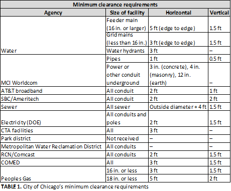
The continuous maintenance and improvement of these utility networks require an immense amount of coordination, especially for areas with a high population density. In these areas, one critical factor of utility design is avoiding utility conflicts, especially in metropolitan areas with a high utility density. Most municipalities will require minimum horizontal and vertical separation requirements for each utility.
As shown in TABLE 1, Chicago has specific standards for horizontal and vertical clearance requirements for all utility installations. For Peoples Gas’ designs, all projects are required to retrieve existing utility information from Chicago. Once the existing utility information has been obtained, a survey of the project area is completed to conform to SUE Level C. After both items have been shown on drawings, conflict analysis can occur, and the running line of the proposed gas main be safely designed.
 |
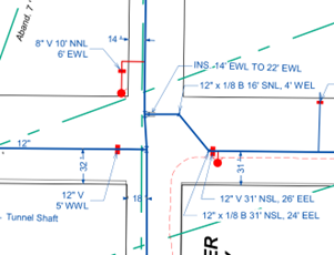
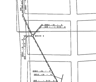
As shown in FIGS. 1 and 2, the level of information provided can vary drastically. FIG. 1 shows a clear water main atlas page, with specific right of way (ROW) dimensions and fittings such as valves, tees, elbows and hydrants. FIG. 2 provides a general idea and scope of the location of the telecom utility but does not contain any dimensions or scale that ties the underground asset to a specific location in the field.
 |
|
FIG. 1. Chicago water main record. |
 |
|
FIG. 2. Chicago telecom record. |
Using utility records provided in FIGS. 1 and 2, in combination with an aboveground survey, would qualify as SUE Level C even though both records provide drastically different levels of information. It is important to understand that SUE Level C is only as accurate as the information provided on the records.
Chicago may be unique in the sense that there is one governing entity that manages utility coordination. Utility coordination in the surrounding suburbs, Nicor Gas’s territory, follows a different path. The amount and age of existing utility information available is completely dependent on the municipality, ranging from old physical records to modern GIS systems. As a result, the detail and amount of existing information shown on natural gas design plans can vary widely, which can put additional risk on operators and contractors during construction to properly locate and avoid utility conflicts.
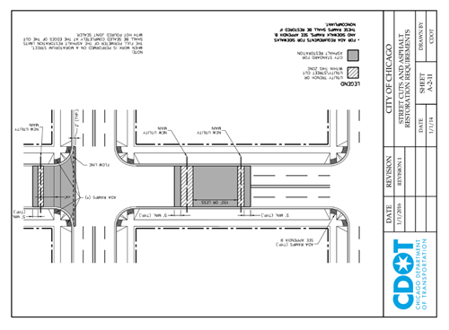
Impacts of variation in regulations. While there is little debate that regulations play a critical role in ensuring the safety of all natural gas pipeline operations, municipal regulations directly affect the cost of projects and programs. For example, as referenced in the “natural gas regulations” section of this article, Chicago requires all natural gas pipe within its jurisdiction to be installed via the open cut method. Per the 2019 Rules and Regulations for Construction in the Public Way, all openings in the public way must also be restored per Chicago Department of Transportation (CDOT) standards.6 FIG. 3 shows an example of the limits of restoration based off various opening within a sample roadway.
 |
|
FIG. 3. Sheet A-2-11 street cuts and asphalt restoration requirements. |
FIG. 3 shows typical examples of how a simple street crossing with a natural gas pipe can impact restoration limits. First, if two openings are located within 150 ft of each other, the area between those openings must be restored. Second, if a new utility is being installed within 5 ft of an intersection, the intersection must be restored up to the flow line of the adjacent street. Since natural gas pipes are required to be open cut in the roadway, these restoration standards must be followed. Experienced engineers working on natural gas designs in Chicago understand these requirements, and, in turn, use judgement to minimize restoration impacts. For example, if there are gas mains within 150 ft of each other, in many cases, they will be moved farther apart to save on restoration costs.
In contrast to Chicago, Will County, Illinois has different regulations that also considerably impact the cost of natural gas design in its jurisdiction. Per the Will County utility permit guidelines (dated February 2019), Will County does not allow roadway impacts for any newly installed facility without the written permission from Will County’s Department of Transportation (DOT).7 Natural gas facilities are required to be directionally bored across the roadway to minimize impacts to traffic and street restoration. Will County also does not allow the abandonment of underground facilities, requiring contractors to remove abandoned natural gas piping once it has been retired. The cost of the removal falls on the owner of the facility.
Current solutions. For engineering designs to be effective, information shown on design drawings must be reliable, accurate and easily accessible.
For Chicago, the Office of Underground Coordination (OUC) is responsible for the protection of the surface and subsurface infrastructure from damage due to planned and programmed construction, installation and maintenance projects. Any proposed projects for new construction and installation work within the city must be processed through the OUC. The OUC is comprised of 27 reviewing utility members, consisting of both city agencies and private entities who review existing utility information and proposed projects to determine the effect that specific requests will have on their facilities.8 The OUC acts as a centralized hub that disseminates existing utility information and provides coordination between all its members to minimize conflicts in the field during construction.
The OUC process can be separated into two different stages: Information retrieval (IR) and existing facility protection (EFP). During the IR process, each representative from the participating companies has 30 calendar days to respond to the proposed underground work. Each reviewing utility member—consisting of but not limited to water, sewer, telecom, electric and natural gas utilities—provide information for the requested project area straight from their records. Combined with Chicago’s requirement to survey all project areas, this ensures that all submitted projects to the city adhere to SUE Level C standards.9
During the EFP process, each of the utility representatives will review the submitted project. Based off the proposed design and existing information shown, will authorize the permit, reject the plans due to a conflict or mark that their facilities are not located in the project area. Each utility reviewer will provide comments that must be addressed until a permit can be authorized. These comments can help to address any concerns or questions that arise due to older or less accurate records. Only once all participating members authorize the permit, then a project can be approved and issued for construction. Accurate and reliable information allows engineers to provide conflict analysis to mitigate risk of damage during construction.
While this article primarily focuses on design, it is worth mentioning that design plans often require contractors to utilize their local 811 number before they dig to electronically locate any utilities in the project area. Electronic locates (SUE Level A) completed just before construction compiled with accurate information on the design drawings have shown to lower the risk of change orders and damage to other facilities.
Recent federal regulation has also been a driver for improved accuracy and reliability of information. CFR Part 192.607 reads: “Records established under this section documenting physical pipeline characteristics and attributes, including diameter, wall thickness, seam type and grade (e.g., yield strength, ultimate tensile strength, or pressure rating for valves and flanges, etc.), must be maintained for the life of the pipeline and be traceable, verifiable and complete.10 While this regulation applies specifically to steel transmission natural gas pipeline, the key words are traceable, verifiable and complete. As technology continues to evolve, natural gas operators have already turned to GIS systems to help adapt to CFR 192.607. Starting on July 1, 2020, natural gas operators have 14 yr to become compliant with CFR192.607. While it remains to be seen how GIS systems will evolve in 14 yr, the PHMSA’s goal is clear; provide regulation to improve the accuracy, reliability and availability of pipeline information.
Takeaways. Natural gas has become an integral part of everyday life in society. Federal and municipal regulations strive to provide safer and more reliable systems to minimize catastrophes. Design engineers play a critical role in providing safe designs to minimize field changes and risks. It is critical for natural gas design engineers to understand where their information comes from and how it can be affected by current regulation. Engineering judgement is required to determine when existing information must be supplemented with advanced locating techniques. An understanding of federal and municipal regulations is crucial to maintain a balance between a cost-effective design and a safe design. GP
LITERATURE CITED
- U.S. Energy Information Administration, “About U.S. natural gas pipelines,” U.S. EIA, 2008, online: https://www.eia.gov/naturalgas/archive/analysis_publications/ngpipeline/index.html
- PHMSA/NAPSR Plastic Pipe ad hoc committee, “Meta-analysis: Cross bore practices,” PHMSA/NAPSR, July 10, 2014, online: https://www.phmsa.dot.gov/sites/phmsa.dot.gov/files/docs/technical-resources/pipeline/gas-distribution-integrity-management/66016/metaanalysiscrossborepractices07102014-final-r3.pdf
- City of Chicago, ”OUC review criteria,” Chicago government: Transportation, online: www.chicago.gov/city/en/depts/cdot/supp_info/efp--projects_requiringreview.html
- Nicor Gas, “Our service area,” 2022, online: https://www.nicorgas.com/company/where-we-are/our-service-area.html
- National Conference of State Legislatures, “How states protect pipelines from excavation damage,” NCSL, 2021, online: https://www.ncsl.org/research/energy/how-states-protect-pipelines-from-excavation-damage.aspx#:~:text=Every%20state%20has%20its%20own,the%20part%20of%20the%20state
- CDOT, “Rules and regulations for construction in the public way,” January 2019, online: https://www.chicago.gov/content/dam/city/depts/cdot/Construction%20Guidelines/2019/2019_CDOT_Rules_and_Regs_101819.pdf
- Will County DOT, “Utility permit guidelines,” February 22, 2019, online: www.willcountyillinois.com/County-Offices/Economic-Development/Division-of-Transportation/Permit-and-Access-Regulations/Utility-Permits/FileId/5980
- CDOT, “Office of Underground Coordination,” 2022, Online: www.chicago.gov/city/en/depts/cdot/provdrs/construction_information/svcs/office_of_undergroundcoordination.html
- U.S. DOT Federal Highway Administration, “Design: Subsurface utility engineering,” April 2018, online: www.fhwa.dot.gov/programadmin/sueindex.cfm
- ECFR.gov, “Code of Federal Regulations,” October 2022, online: www.ecfr.gov/current/title-49/subtitle-B/chapter-I/subchapter-D/part-192?toc=1
Samuel Miller is Vice President of Gas Engineering for Milhouse Engineering and Construction. He is the author of “Regulation and Natural Gas Design,” which is a resource for engineers in the design space on how federal and municipal regulations can affect natural gas design. The work focuses on four main points: natural gas regulations and historical events, critical factors that affect natural gas design, impacts of variations in regulation, and current solutions to improve information accuracy on natural gas design drawings.


Comments