
High-temperature hydrogen attack, accelerated by a fire incident
This article investigates the damage mechanism of a 2-in.outer diameter (OD)low-alloy Platformer furnace thermowell tubein a refinery. The thermowell tube that was connected to the outlet header failed after 4 mos in operation. The loss of primary containment releaseda mixture of hydrotreated hydrocarbons (naphtha) and hydrogen gases into the atmosphere, which combusted spontaneously within the fire box. The 4-in.OD furnace tubes have been fully re-tubed during the latest plant turnaroundwith upgraded metallurgy—T22[2.25 chromium (Cr)-1 molybdenum (Mo)]to T9(9Cr-1Mo)—because of creep and external sulfidation damages. Based on the laboratory metallurgical examination, it was observed that the low-alloy thermowell tube failed by high-temperature hydrogen attack (HTHA) on the thermowell tube base metal along the 6 o’clock position.
Fire at the CCR Platformer unit. On April 2, 2020, a fire was observed at the first inter-heater outlet header on the continuous catalytic regenerator (CCR) Platformer unit. The CCR Platforming unit was commissioned in 1985. There are four heaters in the Platforming reaction section. During the unit’s turnaround in November 2019, all four charge and inter-heaters were completely retubed, including the 22-in. inlet/outlet headers. The heater tubes were upgraded from T22 (2.25Cr-1Mo) to 9Cr-1Mo (T9). In addition, the new header line’s wall thickness was increased from schedule 30 pipe size to schedule 60. The materials were upgraded to overcome chronical creep and external sulfidation damages.
The fire was noticed from the outlet header box toward the end flange area. The fire was caused by two leaks found in a 2-in.thermowell tube nozzle attached to theoutlet header. A process review was conducted on the furnace nozzle failure to investigate the possible root causes. The fire was attributed to a leak comprised of a mixture of hydrocarbons (naphtha) and hydrogen gases which combusted spontaneously within the fire box. The unit was immediately depressurized and handed over for repair and investigation.
An initial visual inspection was conducted. Looking inside the fire box from peep holes, signs of flames could be seen emanating downwards from the roof openings where the tubes pass to connect to the outlet header. This observation indicated that the heat source was contained inside the header cover at the furnace top and not from the internal tubes. The hydrocarbon/hydrogen mixture was self-igniting at the locations where oxygen was available. It was found that the fire was from the 2-in. thermowell tube that failed after 4 mos of service—it operated from December 12, 2019–April 2, 2020. The process parameters were investigated over the operation period and no abnormalities were observed. The operating parameters are provided below:
- Design code:Coil: API560, header: ASME B31.3
- Process fluid: Hydrotreated naphtha and hydrogen mix in vapor
- Operating Pressure: 10 barg
- Inlet/outlet operating temperatures:470°C and 543°C, respectively
- Hydrogen partial pressure: Approximately 8 bar (800 kPa).
A crack was observed that extended along the toe of the weldolet-to-header girth weld on the weldolet connection. Another rupture indication was detected along the horizontal thermowell tube at a 6 o’clock position inside in the header box (FIG. 1). The rest of the furnace tubes, piping, structure and appurtenances were unaffected.
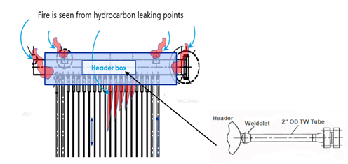 |
| FIG. 1. Platformer furnace low-alloy tubes (A) connected to the outlet header; 2-in. OD low-alloy (1.25 Cr-0.5 Mo) thermowell tube (B). |
A cut portion of the failed thermowell2-in. OD tube, attached to the 22-in.OD outlet header of the Platformer furnace, was metallurgically analyzed to define a damage mechanism. The 2-in. diameter thermowell tube was comprised of P11 (1.25Cr-0.5Mo) low-alloy steel material.
Initial assessment: Potential damage mechanism and sequences of failures. Two major indications were observed visually along the defective thermowell Platformer furnace tube, as indicated in FIG. 2. These included the following:
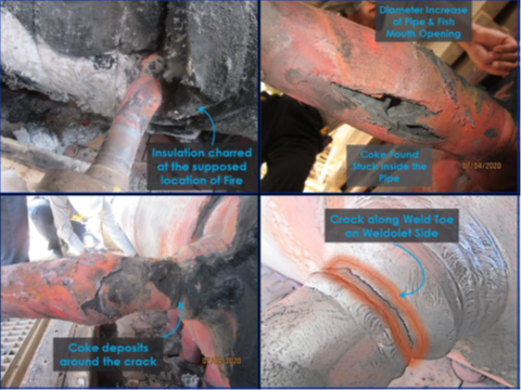 |
| FIG. 2. A view of the 2-in. OD thermowell low-alloy tube’s base metal rupture and fitting weld crack. |
- Crack‐like flaw damage running along the toe of the weld between the weldolet fitting and header. This crack could be attributed to several causes, including, but not limited to, thermal or vibrational fatigue, hydrogen, weld quality or overstress after the volumetric flow rupture accelerated by inherited stresses around the weldment because of an improper localized pre-heat weld treatment application.
- Volumetric-like flow damage (fissuringrupture) along the 2-in. tube base metal. This damage is likely attributed to HTHA, which is a time-temperature-pressure function. This damage mechanism results in degradation of material properties at elevated temperatures, leading to sudden and catastrophic failure. This failure usually occurs after an incubation period, which can vary from a few hours to many years depending on the severity of the environment and the integrity of the base metal. Hydrogen embrittlement and blistering were ruled out since they occur at low temperatures. Based on the initial evaluation, creep failure was also disregarded since creep is formed in the heat affected zone (HAZ) after long-term exposureto elevated temperatures in the presence of constant load. Therefore, creep damage was not suspected to have occurred.
Two scenarios were addressed:rupture followed by cracking or cracking followed by rupture. From an operation parameters perspective, the maximum outlet temperature reached at the outlet header was below 530°C. As per the Nelson Curve in FIG. 3, the metal skin temperature should be exposed to an operating temperature greater than 600°Cat the reported ppH2 of 8 bars (0.8 MPa)prior to initiating the HTHA damage mechanism. This fact rules out the first scenariothat rupture was the first damage since it is unlikely to have occurred at lower temperatures with the reported relatively short incubation period. Secondly, the insulation around the weldolet crack area was found charred,indicating a continuous burning by jet flame. The ceramic fiber insulation was fire resistance material. Charringand burning can occur if temperature exceeds 1,260°C.
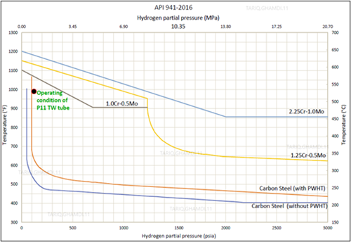 |
| FIG. 3. Nelson Curve indicating the suitability of tube material selection during normal operation, based on operating conditions. |
Moreover, the outlet process temperatures of the four fired heaters and the outlet process headers' temperatures were analyzed and compared. Based on the temperature trends and values, the daily difference between the outlet temperatures of each furnace and the outlet header was quite normal (i.e., 1°C–2°C)except for the defective furnace which indicated a 3°C–4°C difference. The temperature difference between the outlets fired furnace and the header line is indicative of crack symptoms inside the header's box, which likely started 10 d before the major fire, as indicated in FIG. 4.The reactors’ inlet and outlet differential temperatures were evaluated and found to be within the normal operating ranges, trending in the same manner for the entire analyzed period.
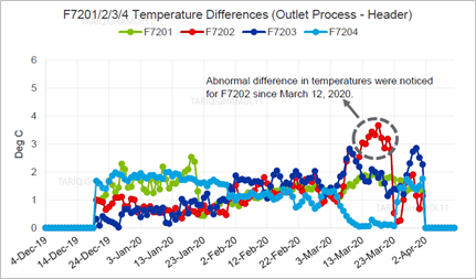 |
| FIG. 4. Absolute difference in temperatures between the outlet process and header. |
The operating pressure trends for the Platforming reaction loop were also analyzed and were within normal operating ranges. The four reactors’ differential pressures were within normal values, with no signs of pressure buildup. The reactor’s outlet pressure was maintained in the normal range of 10.3 barg–10.5 barg with no abnormalities, as shown in FIG. 5. In addition, the hydrogen:hydrocarbon ratio was examined as another process indictor and was found to be adequately maintained at around 2.6mol/mol for 4 mos prior to the date of failure.
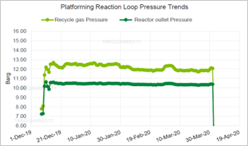 |
| FIG. 5. Platforming reaction pressure trends. |
This preliminary evaluation concluded that the second scenario—the weldoletcrack occured first, followed by the rupture—was the most reasonable sequence of events. The fire was caused by the combustion of leaking gases from the weldolet crack and raised the thermowell tube metal temperature, which enhanced the stress-rupture associated with internal pressure and reduction in tube strength. The fire potentially accelerated the carburization/decarburization and HTHA damage mechanisms along the thermowell tube.The following details the metallurgical investigation conducted on the failed thermowell tube welded to the outlet header.
HTHA phenomena. This kind of damage is an insidious condition that can occur in carbon and low-alloy steel equipment and piping exposed to hydrogen at high temperatures. Hydrogen molecules dissociate at high temperatures to form atomic hydrogen, which can diffuse through steel. Then, atomic hydrogen reacts and combines with unstable metal carbides to form irreversible methane (CH4) which cannot diffuse out of the steel. These voids normally grow slowly. However, HTHA can be accelerated based on the severity of the environment under the combined effects of increasing operating temperature, high hydrogen partial pressure, applied and inherited stresses,and lowquality of the original base metal. This damage cannot be easily predicted since the failure can be very localized.1,2,3
The operating limits for steels can be defined using operating temperature and the hydrogen partial pressure, as discussed by the Nelson Curve in API recommended practice (RP) 941. As reported, thethermowell tube operating temperature was approximately 525°C, and the hydrogen partial pressure was 8 bara (0.8MPa). Based on the information provided, the specified material (P11)was considered suitable because the operating conditions confirmed that the existing tube material stayed below the Nelson Curve limit. Although Nelson Curves are sets of graphs that delineate the safe operating states, there have been several cases where HTHA took place below the Nelson Curve. Using API RP 941 as a guide, FIG. 3 illustrates the tube material suitability for service under the existing operating conditions.4
Laboratory tests and analysis. Due to material unavailability, the exiting defective weldolet fitting was not completely removed. This fitting was left attached to the header line. The crack was removed, and the fitting end was beveled and reused. A thin cut portion of the cracked weldolet atthe 2-in. OD weldolet was also metallurgically analyzed to determine the possible damage mechanism. FIG. 6 shows the defective weldolet—checked by a dye penetrant test—and a fine cut piece of cracked weld.
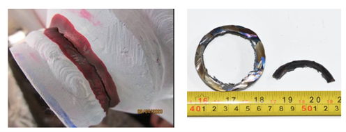 |
| FIG. 6. View of the weld crack (A) that extended from the 12 o’clock position to the 5 o’clock position, and the thin cut of the weld fracture surface (B), which was subjected to a metallurgical examination. |
FIG. 7 shows the 2-in.themowell tube, asreceived in the testing laboratory for metallurgical analysis. A hardness measurement was performed along the affected area, along with a thicknessmeasurement using a micro Vickers’s hardness tester at a load of 0.5kilogram-force (kgf). Thickness measurements at the ruptured area and away from the defect were carried out. A chemical examination was also conducted using PMI and an optical emission microscope to validate the material’s specification. Cross-section specimens were examined under a stereo binocular microscope to produce a three-dimensional visualization of the sample. In addition, metal samples were prepared for metallographic examination under optical microscope and scanning electron microscope/energy dispersive spectroscopy (SEM/EDS) to investigate the microstructure, cracks propagation and morphology.
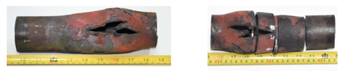 |
| FIG. 7. View of the ruptured tube section (A), which was cut into pieces for the metallurigical examination (B). |
Results and discussion. A review of the operating process conditions for the investigated period were found normal, as well as with the design operating window of the fired heater.
First defect: Weld crack between the weldolet and tube. The metallurgical examination of the fine-cut specimen of the damaged weld revealed that the crack was attributed to low-quality welding filler and welding performance. FIG. 8A shows that themetallographic examination indicated significant signs of inclusions and foreign particles. The SEM revealed multi-intergranular/transgranular cracks initiated from the inclusions, as explained in FIG. 8B. The EDS analysis (FIG. 9) shows a high content of carbon, nitrogen and oxygen with detrimental corrosive elements (i.e., sulfur, chlorine, sodium) on the fracture surface, resulting in a brittle weld defect.
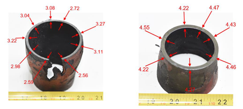 |
| FIG. 8. Thickness values of the 2-in. diameter thermowell tube’s (A) damaged/bulging area and away from the unaffected/bulging area (B). |
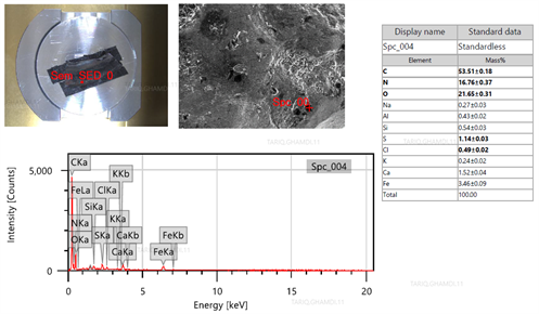 |
| FIG. 9. EDS analysis fo the fractured surface of the cracked weld. |
As previously illustrated in FIG. 4, the crack extended deep and straight along the weld toe between the 12 o’clock and 5 o’clock positions. Based on the site evaluation and crack morphology, the failure was classified as a fatigue crack. Excessive stresses on the weld joiningthe weldolet and the thermowell tube were anticipated due to supporting bar restraint, which hinders free expansion and contraction of thethermowell tube and limits its thermal movement with respect to the main header. This substandard design resulted in a brittle fatigue crack and subsequent a localized fire inside the fire box.
As per design, the header line, the box cover and thermowell nozzle moved 116 mm in the east direction. However, the visual inspection revealed that the box cover of the thermowell tube was tilted 10°–15° from the horizontal position. The direct touch between the box cover and the thermowell tube exert welding load on the extended arm of the thermowell tube, as well as restrict the movement load by the thermowell box assembly.
The concern of fatigue failure due to vortex wake frequency induced vibrations was evaluated. This assumption was exempted since wake frequency induced vibration is a valid concern in high-velocity services. However, fatigue failure due to this cause would be expected at the thermowell flange connection, not at the nozzle weldolet. All thermowells did not historically experience fatigue damage because they do not operate in the high risk (0.8–1.2) range for frequency ratio, as per ASME PTC 19.3. Therefore, this factor should not be a continuator to the failure of the thermowell tube weldolet.
Specifying thermowells at the Platforming furnace outlet is a common practice in the industry. However, it is not common practice to also locate a thermowell in the middle of the outlet header. There is no need or use for the data provided by this intermediate temperature point. This may be old design practice for CCR Platforming heaters, but not recognized by main CCR licensors as there are no essential data provided by these temperature points. The addition of unnecessary equipment provides an opportunity for failure without any associated benefit for monitoring heater performance. Therefore, they should not have been included in the design.
It is believed that the crack was developed due to an external load on the nozzle caused by the header box interference during the header’s thermal expansion, which restricted the free movement of the thermowell tube, resulting in thermal fatigue failure. In addition to thermal fatigue, an unsatisfactory weld quality at the 2-in. weldolet was identified by metallurgical analysis, which could significantly contribute to the crack under the effect of thermal expansion and contraction load.
Second defect: Thermowell tube rupture. Based on the test results, the rupture failure was attributed to HTHA damage mode. HTHA is the result of hydrogen dissociation and dissolve in steel, and then reacting with the carbon in steel to form CH4 gas. This reaction drewcarbon out from the material and resulted in decarburization and a significant thickness reduction, detrimentally accelerated by rupturing, as indicated in FIG. 10.
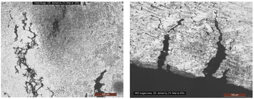 |
| FIG. 10. Branching cracks (A) extended along the decarburized steel. Deep cracks (B) initiated from the ID surface. Decarburization and intergranular cracks were caused by hydrogen depletion from the non-stable iron carbides. |
Signs of surface and internal decarburization phenomena were observed, which are indicative of HTHA. It should be noted that high temperatures and low hydrogen partial pressures typically result in surface decarburization, while lower temperatures and high hydrogen partial pressure favors internal decarburization within the wall thickness. Both conditions were observed, which may imply to non-consistent operation conditions. With time, CH4 pressure still increased at preferential sites at a rate that depends on carbon activity and temperature. Increasing pressure promotedthe extension of defects and appearance of macro cracks or fissures. Intergranular branching cracks and connecting cracks were also observed.
HTHA damage was accelerated by the external heat factor, resulting from the weldolet crack and subsequent leak and flame inside the fire box. Without this external heat source, this failure may not occur due to the short incubation period of hydrogen, knowing that the operating temperature and hydrogen partial pressure indicate safe operating condition, setting below the operating limits, defined by the Nelson Curve in API recommended practice (RP) 941 for P11 low-alloy thermowell tube materials (1.25Cr-0.5Mo).
Decarburization phenomena associated with base metal thinning at the bulging area was reported, which revealeda high possibility of CH4 formation. This failure mode occuredwhen atomic hydrogen reacted with unstable carbides in the steel to form CH4 gas. The formation of CH4caused gas pockets which led to material degradation, the development of voids and catastrophic failure. This theory was supported by high carbon content—indicated on the EDS (FIG. 11)—on the fracture surface. The intergranular cracks, the macro fissuring microstructure surface decarburization and bulge along the thermowell pipe are strong evidence for the occurrence of HTHA failure.
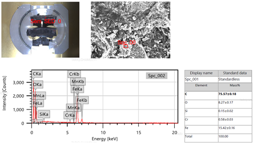 |
| FIG. 11. EDS analysis for the base metal fracture surface. |
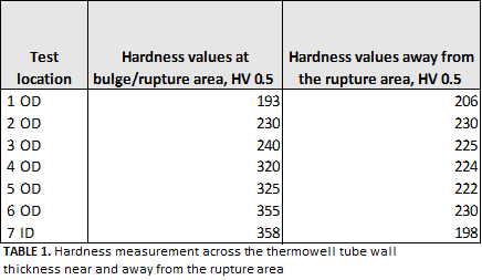
The hardness was also measured across the wall thickness of the polished 2-in.OD thermowell ring samples, extracted at different locations, adjacent to the rupture location at and away from the bulged area at equal distances. The hardness tester was checked by a standard block before measuring the hardness of the tested sample—in compliance withASTM E92. The room temperature was approximately 23°C at the calibration of the hardness tester machine. The hardness values showed higher hardness readings at the damaged area vs.the undamaged zone, which indicated the material exhibited poor ductility at the ruptured area. In addition, the hardness measurement at the rupture area increased. The increase in hardness indicated signs of carburization—as a result of hydrocarbon dissociation—caused by the heat of the combustion fire. The hardness details are described in TABLE 1. Additional hardness measurementswere conducted near the rupture area. The hardness values were reported in the range of 179 HV–188 HV, which is lower than the average hardness value of the unaffected thermowell tube base metal (200 HV–230 HV).
 |
It should be noted that metal catalyzed coking (MCC) is another common phenomenon occurring in reforming units in lowhydrogen partial pressures (> 620 kPa), above 480°C and with a stagnant flow. MCC occurswhen the metal surface metallurgy reacts with the hydrocarbon feed to produce carbon-containing deposits which buildup on the pipe’s inner diametersurface. This type of damage is unavoidable in reforming tubes if sulfur content in the feed is very low. These carbon containing deposits can build up to a level where they are detrimental to the process by creating, for example, pressure drop issues, blocking off catalytic sites, hindering the transfer of heat, and, most importantly, deteriorating the material’s mechanical properties. MCC is also an indication that the plant or process metallurgy is undergoing metal dusting and possibly surface carburization, as well as through-thickness decarburization phenomena. Therefore, a high probability is that MCC wasformed in the 2-in.nozzle and contributed to the thermowellpipe rupture.
To overcome any potential failure due to MCC, the refiner was advised to inject organic sulfur (e.g., dimethyldisulfide) to the CCR feed to maintain a minimum of 0.2 wtppm sulfur in the feed to adequately passivate the metallurgy of a CCR reformer on a continuous basis. Operating a CCR Platforming unit with very low sulfur in the feed may lead to MCC in the reactors and/or carburization of heater tubes. In thisfailure case, MCC would not be significant based on the partial pressure of hydrogen and operating temperature, slight carburization and dusting of the reformer tubes (including thermowell tubes).
Takeaway. The operating conditions of the Platformer furnace for 5 mosprior to the incident were trended and found to be normal and within design specifications. Based on field investigations, metallurgical examinations and process parameters evaluations, the major fire was associated to rupture of a thermowell tube. This rupture was caused by leaking gas from a brittlethermowellweldolet crack. The leaking weldolet resulted in a fire inside the header box. This crack was attributed to thermal fatigue. It was noticed that thermowell tubes were installed in the middle of the outlet headers for all four CCR reforming furnaces, which is not in line with CCR licensors’ practices. These tubes were found under a restraining condition against the header box cover and associated with header thermal expansion and movement. The refinery was advised to remove the non-standard thermowell instrument tubes in the middle of the outlet headers, especially if they are not serving specific and well-known process requirements.
Based on metallurgical examinations, the rupture of the 1.25Cr-0.5Mo tube was attributed to HTHA, although the operating parameters were below the Nelson Curve limit, and the incubation time was considered short. This failure occurred due to exposure of the thermowell tube to abnormal high temperatures caused by the combustion of leaking gases from the adjacent weldolet crack. The fire, developed by the weldolet crack, lasted for about 10 d,resulting in a significant increase in the tube skin temperature, which potentially promoted the formation of MCC and eventually accelerated the initiation of HTHA along the thermowell tube’s body. This mode of failure was determined based on the crack morphology and metallurgical examinations. This sequence of failure was supported by field visual inspection and assessment. GP
LITERATURE CITED
- Pillot, S.and L. Coudreuse, “Hydrogen-induced disbonding and embrittlement of steels used in petrochemical refining,”Gaseous Hydrogen Embrittlement of Materials in Energy Technologies, December 2012.
- McLaughlin, J., J.Krynicki, and T. Bruno, “Cracking of non-PWHT'd Carbon Steel Operating at Conditions Immediately Below the Nelson Curve,” ASME 2010 Pressure Vessels and Piping Conference, Fairfax, Virginia, 2010.
- U.S. Chemical Safety and Hazard Investigation Board, “Investigation Report:Catastrophic Rupture of Heat Exchanger, Tesoro Anacortes Refinery, Anacortes, Washington, April 2, 2010,” May 2014, online: https://www.csb.gov/tesoro-refinery-fatal-explosion-and-fire/
- API RP 941, “Steels for Hydrogen Service at Elevated Temperatures and Pressures in Petroleum Refineries and Petrochemical Plants,”API, February 2016.
 |
Nayef Al Ghamdi is a Process Engineer with the Process & Control Systems Department of Saudi Aramco. He has 12 years of experience in refinery operations, technical support and technologies development. He joined Saudi Aramco in 2011 as a process engineer in the Reforming & Basic Petrochemicals group and later worked in supporting Ras Tanura Refinery operations. He earned a Bachelor’s degree in chemical engineering from King Fahad University of Petroleum & Minerals and recently awarded a master's degree of Chemical Engineering from Cornell University.


Comments