
A new hydraulic turbine approach to increase LNG production and efficiency
Expanding liquid hydrocarbons with hydraulic turbines in place of control valves offers thermodynamic benefits that can be effectively used in all LNG liquefaction processes, including the common propane precooled mixed refrigerant (C3MR) process.Hydraulic turbines provide additional refrigeration that can be efficiently used to:
- Increase production at the original LNG temperature
- Reduce refrigeration power to achieve the original production
- Reduce end-flash by producing colder LNG.
Recent turbine design advancements directly improve reliability and further increase LNG production.A new turbine offering from the authors’ company incorporates these developments with:
- Adjustable inlet nozzles that permit high efficiency over a wide operating range without the need for a variable frequency drive
- Integration of well-referenced components from the air separation and oil and gas industries
- Capability to startup using warm gas, eliminating the liquid cooldown and cold soak.
This article first discusses the process benefits for using hydraulic turbines in a nominal 4.5-MM metric tpy example C3MR process, and then how recent design advancements further improve the owner’s bottom line.
LNG hydraulic turbine benefits.The first benefit hydraulic turbines provide is in increased production.The additional refrigeration provided by hydraulic turbines can be used to produce more LNG at the original temperature—an option that directly increases operating revenue.Generally, production increases 1%–2% when a hydraulic turbine is added to the process.If hydraulic turbines are added to both the LNG and MRL circuits, the total production increase is 2%–4%. TABLE 1 summarizes the financial benefits for using MRL and LNG hydraulic turbines when maximizing production for a nominal 4.5-MM metric tpy example plant with the installed refrigeration power.
 |
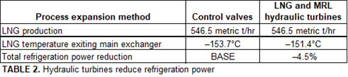
The second benefit hydraulic turbines provide is in refrigeration power reduction.Less refrigeration power is required because hydraulic turbines give a warmer LNG temperature leaving the main cryogenic heat exchanger (MCHE).For a fixed production, LNG refrigeration power can be reduced when hydraulic turbines are used,as shown in TABLE 2.
 |
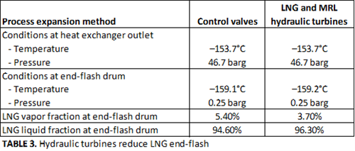
The third benefit hydraulic turbines provide is in sub-cooling.The additional refrigeration provided by the hydraulic turbines can be used to produce colder LNG.The subcooled LNG generates less vapor when its pressure is reduced in the end-flash drum, as shown in TABLE 3.
 |
Reduced end-flash vapor increases the liquid production.For LNG priced at $5/MMBtu, the production increase is valued at approximately $20 MM/yr for the example 4.5-MM metric tpy plant.
Another benefit hydraulic turbines provide is electricity generation.Hydraulic turbines extract work from the process fluids, and that work is converted to electricity.This inherent benefit can be utilized by supplementing refrigeration power, offsetting site power generation or exporting power.For the 4.5-MM metric tpy plant, the LNG and MRL hydraulic turbines generate a total of 2.3 MW.At $0.06/kWh, this power is valued at approximately $1.12 MM/yr.
The example 4.5-MM metric tpy process clearly shows the financial benefits of using hydraulic turbines in the liquefaction process.
LNG HYDRAULIC TURBINE CONFIGURATIONS AND FEATURES
A conventional LNG hydraulic turbine is directly coupled to a generator on a common shaft oriented vertically.The generator is an induction motor, and electricity is produced when the generator is synchronized to the site’s grid and the turbine is in operation.The generator and turbine are submerged in process fluid, and the process flow is typically bottom to top, thereby avoiding vapor entrapment in the rotating assembly.The generator is cooled by the same process fluid that is expanded in the turbine; therefore, no mechanical shaft seals are required to separate the process fluid from the rotating electrical and mechanical components.The entire turbine/generator assembly is housed inside a pressure-containing vessel, which is equipped with purged penetrations for all electrical and instrument connections.
Typical configurations and operation.Two hydraulic turbine configurations are used in the LNG industry: fixed-speed and variable-speed.Under all conditions, head loss (differential head) increases with flowrate.Turbines are typically designed for the discharge pressure to be 2 bar–3 bar above the fluid bubble point.Increasing flowrate above design increases the head loss over the turbine, which reduces the discharge pressure.If the discharge pressure is below the bubble point, vapor will form,giving a two-phase outlet—a condition that is avoided.
The fixed- and variable-speed configurations handle a flowrate increase differently.A fixed-speed machine has only two options for increasing flowrate:
- Increase the differential head across the machine by decreasing the outlet pressure, thereby moving conditions closer to bubble point
- Bypass the turbine with some flow through an external control valve.
A variable-speed machine has an inherent benefit for handling a flowrate increase: it can modulate its speed to achieve the same differential head.Using a variable frequency drive, the turbine generator can operate at asynchronous electrical frequencies.This feature allows the variable-speed turbine to handle the flowrate increase without moving outlet conditions closer to bubble point.
Variable frequency drive.The field installation for the fixed-speed and variable-speed configurations are similar with one exception: the variable-speed turbineuses a variable-speed drive [also called a variable frequency drive (VFD)].The VFD conditions the electrical power that is generated at asynchronous frequencies and converts the signal to line frequency.Adding the VFD to the turbine system naturally reduces reliability because it is another component that can—and will—fail.
Startup cooldown requirements.Typical LNG industry hydraulic turbines require cooldown prior to startup, typically conducted with a “soak in place” methodology.This requires incrementally filling the housing that holds the turbine and generator with cryogenic fluid, then allowing the system to cool to a target temperature.This cooldown is a12 hr–24 hr duration.
ADVANCEMENTS IN HYDRAULIC TURBINE DESIGN
General arrangement.The configuration of the new offering differs from the conventional LNG hydraulic turbine—it is connected to a generator with a single shaft in a horizontal arrangement (FIG. 1).This arrangement can be divided into three main sub-assemblies: the expander mechanical center section (MCS), the gearbox and the generator.A differentiating feature is separating the gearbox and generator from the cryogenic process stream.This avoids the need for the entire shaft, bearings, seals and other components in the expander MCS to be exposed to cryogenic temperatures and the natural large thermal gradients that can significantly change clearances and impact operation.Locating the bearings outside of the process fluid eliminates the inherent potential for bearing contamination that exists with process lubricated bearings.
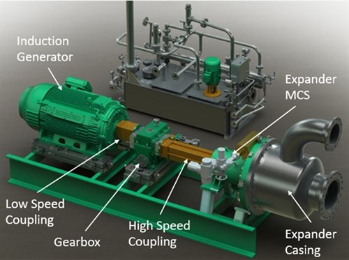 |
| FIG. 1. General arrangement of the new turbine offering. |
Adjustable inlet nozzles.The new offering incorporates adjustable inlet nozzles to increase the turbine’s flow range.The inlet nozzles direct the process fluid flow into the expander impeller (FIG. 2).By adjusting the throat, or the distance between the adjacent nozzles, the flow through the expander can be controlled while maintaining the inlet and outlet pressures of the turbine.The nozzle position is typically controlled by the DCS via an electric actuator.
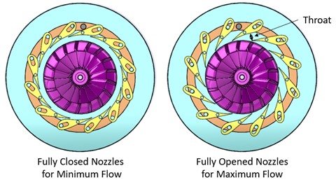 |
| FIG. 2. Open and closed positions of the adjustable inlet nozzles. |
INTEGRATING WELL-REFERENCED COMPONENTS: BEARINGS, SEALS, GEARBOX AND GENERATOR
Bearings. Essential to reliability and performance, bearings support the rotating shaft and impellers.The new turbine offering employs combination journal- and thrusttilting-pad bearings, which are well referenced in compressors, gas and steam turbines, pumps, turboexpanders, turbochargers and other equipment.The tilting-pad bearing has numerous individual tilting pads that support the shaft, either radially or axially, mounted into a bearing shell.Lubricating oil flows through the bearing shell onto the tilting pads, where a thin film of oil separates the shaft and bearing, preventing contact.
Tilting pad bearings are well-suited for hydraulic turbines, which operate at high speed and load.Tight bearing clearances maximize efficiency by enabling close operating clearances between the rotating impeller and stationary shroud.
Seals.The seals used in the new hydraulic turbine offering are well referenced and familiar to the rotating equipment industry.The seals have the following requirements:
- Prevent the process fluid from leaking to the atmosphere or into the lube oil reservoir
- Provide a thermal barrier between the cold process stream and the warm lube oil bearings
- Prevent oil from entering the primary and secondary seals, or the process itself.
The new offering uses a tandem dry gas seal with an intermediate labyrinth sealto meet the first two requirements, and a separation seal to satisfy the third requirement. FIG. 3 shows the seal arrangement.
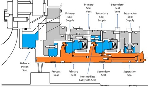 |
| FIG. 3. Tandem dry gas seal with intermediate labyrinth seal. |
To ensure identical composition, the typical seal arrangement uses vaporized process fluid as the primary sealing gas.The seal gas is injected into the primary sealing chamber to supply clean, dry seal gas to the primary seal.Nitrogen, due to its inert nature, is used as the secondary sealing gas and enters between the intermediate labyrinth seal and the secondary sealing chamber.The separationsealprevents oil from entering the tandem seal where the oil could cause damage to the primary or secondary seals.The separation seal typically uses carbon ring seals with nitrogen as the sealing gas.
Tandem dry gas seals are commonly used in a variety of rotating machines that contain toxic or flammable gas.The design and integration of dry gas seals are covered under API Standard 692, which states that if the purchaser does not specify the dry gas seal type, the default requirement is a tandem dry gas seal with intermediate labyrinth.This demonstrates the broad acceptance of this well-referenced technology for applications with similar performance requirements.
Gearbox.The typical operating speeds for MRL and LNG turbines are 3,000rpm–16,000 rpm.In some cases, the turbine will run at the induction generator speed and would be directly coupled to the generator.When the turbine runs faster, a parallel shaft gearbox decreases the turbine shaft input speed to the induction generator speed.Typical applications may use single- or double-helical gearing and can be offered in API Standard 677- or API Standard 613-compliant designs.These gearbox arrangements are common in industry and utilized on numerous equipment offerings from many manufacturers.Compliance with API standards and sourcing from reputable suppliers ensure high reliability and quality.
Generator. By separating the induction generator from the process fluid and its cryogenic temperatures, the new hydraulic turbine offering uses standard induction generators, allowing the purchaser to use suppliers that are well-known, well-referenced and familiar.Many international design standards and guidelines can be applied, ensuring the generator meets the specified reliability and quality.
Startup using warm gas.The new turbine offering uses a significantly different machinery arrangement that permits startup from a warm condition without the need for cooldown.A warm startup is achieved using the following design features:
- The mechanical components that have small clearances are separated from the cryogenic process fluid (FIGS. 1 and 4). Several components (bearings, seals, gearbox and generator) have clearances that can be sensitive to large thermal gradients; by separating them from the process fluid, they are not subjected to large thermal gradients and will not experience the temperature-related clearance changes.
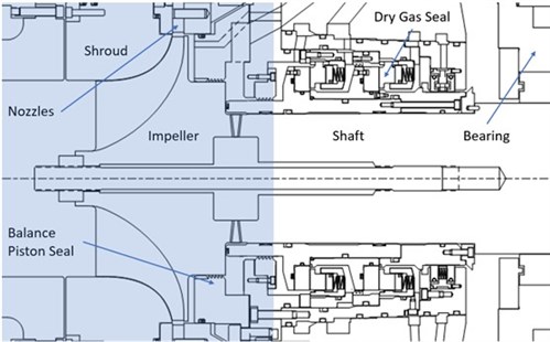
FIG. 4. Process fluid “wetted” components (blue highlighted area).
- The wetted components that contact the process fluid are designed to handle rapid temperature transients.The new turbine offering utilizes the same design techniques and materials of construction used in typical gaseous turboexpanders.Gaseous turboexpanders operate in thousands of installations worldwide, and these machines often start from ambient conditions and rapidly achieve cryogenic conditions in very short time periods.
The cryogenic air separation industry uses hydraulic turbines to extract work by expanding liquid air, and the authors’ company operates several dozen air separation installations in this service.These turbines are similar in design to the new offering and startup using warm vapor, further demonstrating that the warm startup methodology is practical and well-referenced.Eliminating the cooldown increases hydraulic turbine availability to 72 hr/yr–144 hr/yr, thereby increasing revenue by $360,000–$720,000 over conventional hydraulic turbines. This quantification is based on a conventional hydraulic turbine requiring a 12 hr–24 hr cooldown; one startup every two months for a single turbine; $5/MMBtu LNG price (approximately $250/hr per metric t); 20 metric t/hr production increase when running the hydraulic turbines (per TABLE 1).1
Integrating well-referenced components directly translates to lower technical risk and higher onstream time.Operators and maintenance personnel are familiar with these components, leading to less opportunity for human error and reducing the risk of additional down time, as well.
The following case study demonstrates how the hydraulic turbine design advancements lead to increased production.
Case study: Production increase at off-design conditions.This case studyis presented to compare the benefits of using the available hydraulic turbine configurations in a C3MR process.The study incorporates both the MRL and LNG turbines for a nominal 4.5-MM metric tpy plant.
Design conditions capture an operating point in a typically wide range of conditions.This study investigates the LNG hydraulic turbine performance at off-design conditions.In this study, a turbine design is sized for the production at the average ambient conditions (26°C), and the design is rated at cold ambient conditions (7°C)—conditions at which the liquefaction unit produces more LNG. TABLE 4 compares the three hydraulic turbine configurations at cold ambient conditions.
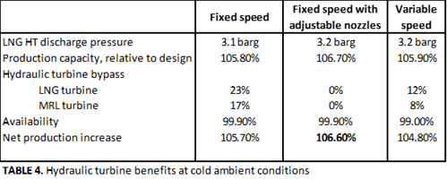 |
TABLE 4 shows the fixed speed turbine with adjustable inlet nozzles gives the highest net annual production for off-design conditions.This study highlights:
- Fixed-speed turbineshave limited capacity above design conditions—the additional flow is bypassed around the turbines.Work/energy extraction is limited to the design flowrate.
- Variable-speed turbinesare capable of processing more flow by reducing the turbine speed, which provides extra refrigeration and increases production to 105.9% of design.The turndown speed is a practical limit for the capacity of the variable-speed turbine.Like the fixed-speed turbine, some liquid bypasses both LNG and MRL turbines, losing potential refrigeration.
- Adjustable nozzles allow the hydraulic turbines to process all additional flow, providing more refrigeration and increasing production to 106.7% of design.
- Fixed-speed turbines have a higher availability, giving a higher net production increase.A system with more components is inherently less reliable.A system with fewer components maximizes equipment availability, thereby maximizing production increases.
Takeaway. This article presents the benefits of a new hydraulic turbine offering for an LNG process.The new hydraulic turbine is fixed speed, which eliminates the cost and availability issues of variable-speed drives.Adjustable flow nozzles can handle a wide range of flowrates, increasing production at off-design conditions.Finally, well-referenced components maximize reliability.This combination of features make this turbine design well-suited for optimizing LNG production and increasing revenue. GP
LITERATURE CITED
- Scott, K., E. Eiswerth,W. Schmidt,S. Farnand and T. Barzeski,“A new hydraulic turbine approach to increase LNG production and efficiency,” Air Products, Gastech, Dubai, September 2021.
ABOUT THE AUTHORS
 |
KERRY SCOTT is responsible for the process design of LNG liquefaction cycles.He has 25 yr of experience in hydrocarbon engineering, including high-temperature hydrogen generation and cryogenic LNG technologies.Since 2012, Scott has been in the LNG Process Technology group, where he has designed coil-wound heat exchangers used in numerous liquefaction cycles.He continues to provide field support through startup, performance testing and process optimization services. Scott holds a BS degree in chemical engineering from Pennsylvania State University.
 |
ETHAN EISWERTH is responsible for research and development of new technologies and process improvements, as well as managing the proposal development and new product development teams in Rotoflow. He has 19 yr of turbomachinery engineering experience after having held numerous engineering roles within the Air Products’ CryoMachinery Department.As a Product Development Engineer, Eiswerth led the development of a new, high-speed, permanent magnet generator-loaded, gas-bearing expander, with power recovery, and managed the development of numerous turbo expanders for various applications.Prior to this, as a Machinery Design Engineer, he led the design and engineering of several turboexpander frames, accessory systems and control systems, and performed commissioning and startup of the equipment on the world’s first operating floating LNG production plant.Eiswerth holds a BS degree in mechanical engineering from Bucknell University and has extensive experience with API-617, API-614, API-670, API-692, ASME B31.3, and ASME BPVC Sections II, VIII, and IX.


Comments