
Soft startup of best practices for commissioning of amine plants
The startup and commissioning of hydrocarbon plants can present unique challenges that, if not anticipated and addressed in the pre-commissioning and commissioning periods, will inhibit plant startup and increase the difficulty of achieving product specifications in a timely manner. This article provides details on potential multiple challenges during commissioning, as well as a method to avoid these challenges by applying a soft startup concept on a massive scale. The acceptance criteria and successful results of the soft startup concept are detailed here.
Plant A sought to avoid or reduce the common commissioning challenges of a new amine system (e.g., gas treatment facility), including foaming, the presence of unwanted debris or materials in piping and vessels, etc. To ensure the short- and long-term reliability of an amine system facility, Plant A elected to implement a soft startup concept on a massive scale, where the amine circuits are filled completely with pure demineralized water (rather than amine), then pressurized by nitrogen (rather than fuel gas) up to the operating pressure. This was completed for multiple safety and reliability reasons to:
- Test system tightness with a safer medium (nitrogen, as compared to fuel gas)
- Debug the associated process control and emergency shutdown (ESD) systems
- Test the functionality and reliability of all rotating equipment
- Clean the system of any remaining debris and suspended solids prior to charging with expensive solvent into the unit
- Limit the potential for future foaming incidents.
During the soft startup, circulation is started in both cold and hot modes to ensure that all debris and suspended solids are removed from the pipe walls, fittings, valves and other equipment and vessels, and the debris and suspended solids are caught by the strainers and filters. This approach was successfully utilized in the other amine units.
Amine system process description—acid gas removal unit. The gas enters the treating train through the inlet filter separator. The separator is provided to remove any particulate matter or traces of liquids that may be received with the incoming gas. Without a spare separator, a bypass valve (sized for full flow) is installed to allow maintenance servicing of the separator.
The gas coming from the inlet filter is fed to the amine contactor for carbon dioxide (CO2) removal. The contactor is a tray column divided in two sections. The bottom amine absorber section consists of trays. The lean amine is fed to the top tray and the rich amine is withdrawn from the bottom of the tower. The upper section of the contactor comprises three trays and is used as a water washing system to absorb any amine entrained in the gas from the bottom absorber section. The second pass reverse osmosis water is circulated around the trays by pumps.
A continuous make-up of fresh reverse osmosis water is fed to the top of the section while excess water is drained from the column water wash chimney tray to the rich amine flash drum. The outlet for the wet sweet gas from the top of the amine contactor is routed out of the gas treating train to the natural gas liquids (NGL) recovery unit.
Rich amine from the contactor bottom is fed to the rich amine flash drum, a horizontal vessel with a top-mounted vertical absorber equipped with random packing. The hydrocarbon gases dissolved in the rich amine are flashed off, washed through the absorber and routed to the thermal oxidizer. As the flashed gases pass through the absorber, any amine entrainment is removed by the counter flow of the water withdrawn from the amine contactor top section. The rich amine coming from the flash drum is heated up through the lean/rich amine exchangers and fed to the amine stripper.
The stripper is a trays column with two once-through exchangers that take feed from the column bottom chimney tray. Heat for the amine stripper reboilers is supplied from the low-pressure hot water system. The gases from the top of the stripper are cooled in the amine stripper overhead condenser and water is condensed in the reflux drum. The acid gas is routed to the CO2 compression unit. Any organic phase present will be separated in the reflux drum and manually discharged to the wet hydrocarbon burn pit.
The reflux pumps return the condensed water as reflux back to the stripper top tray and, during the regeneration cycle, partially to the amine reclaimer. The lean amine from the stripper bottom is routed toward the amine contactor by booster pumps. Before being fed to the contactor, the lean amine is cooled through the lean/rich amine exchanger and the lean amine cooler. The lean amine circulation pumps boost the pressure and return the lean amine to the amine contactor. Pumps route a fraction of the circulating lean amine (~15%) to the precoat filter package, and filtered amine is rejoined to the lean amine flow.
The amine reclaimer is provided to periodically regenerate the circulating amine. A fraction of the circulating lean amine from the booster pumps (~1% of total amine pumped flowrate) is fed to the amine reclaimer. The reclaimer operates at 360°F (182°C) and controls the amine solution boiling temperature by an adequate flowrate of reflux water from the amine stripper reflux pumps. Amine and water are recovered to the stripper as vapors coming from the top of the reclaimer, while degraded amine components are left on the vessel bottom. This sludge pond also receives the amine slurry from the amine precoat filters. The acid gas removal process configuration is shown in FIG. 1.
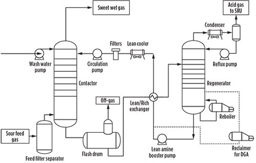 |
| FIG. 1. Typical PFD for an acid gas removal unit. |
Amine system process description—acid gas enrichment unit. The wet acid gas is first cooled in a cooling water chiller and then enters an inlet separator to remove liquid hydrocarbons from the gas stream. The acid gas then enters the bottom of the contactor trayed column and flows upward through the absorber in intimate countercurrent contact with the selective amine solution, where the amine selectively absorbs hydrogen sulfide (H2S) acid gas constituents from the gas stream. Before leaving the contactor, the CO2 gas passes through a water wash section.
The rich amine solution is sent from the bottom of the contactor via the rich amine pump to the lean-rich amine heat exchanger, before entering the top of the stripper column. A part of the absorbed acid gases will be flashed from the heated rich solution on the top tray of the stripper. The remainder of the rich solution flows downward through the stripper in countercurrent contact with vapor generated in a steam reboiler. The reboiler vapor (primarily steam) strips the acid gases from the rich solution.
The acid gas and the steam leaving the top of the stripper pass through a condenser, where the major portion of the steam is condensed and cooled in an air cooler. The acid gas is separated in the reflux drum and sent to the acid gas enrichment unit.
The lean amine solution from the bottom of the stripper column is pumped by a booster pump through a lean-rich heat exchanger and then through air coolers to the top of the contactor. To ensure cleanliness of the circulated selective amine solution in the contactor, a 15% slipstream of the lean solution is passed through a mechanical filtration system.
Acceptance criteria for soft startup. A soft startup can be declared successfully completed when at least two of the following three criteria are achieved:
- The frequency of strainer cleaning is reduced to less than one cleaning activity per strainer every two days.
- Qualitative proof that water samples are getting clearer every operating day for three consecutive days, then stable/no change for an additional day.
- Stable water chemistry parameters are achieved for at least two consecutive days through lab sampling.
PLANT TEST RUNS
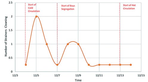
Amine System A. Amine System A was placed under a soft startup on December 4, 2019, and in cold circulation until December 13, 2019. During the cold circulation phase, four of the lean amine cooler bays (50%) were isolated and amine was run through the other four bays to increase turbulence and ensure cleanliness (FIG. 2). After the system was stabilized and the in-service bays were deemed clean, the bays were isolated and the other four bays were put in service. The switching practice continued until consistent readings on the pump strainers were achieved. Following that, amine System A was placed in hot circulation.
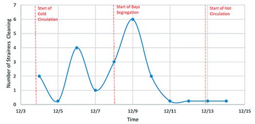 |
| FIG. 2. Frequent strainer cleaning for amine System A. |
As previously highlighted, one of the acceptance criteria of the soft startup is sample bottle clarity. FIG. 3 shows the progression of water clarity by the samples collected from amine System A. It can be clearly seen that the water in the system became clearer and cleaner during the soft circulation period.
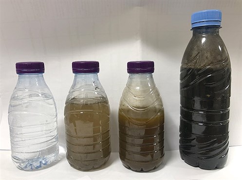 |
| FIG. 3. The progression of water clarity by the samples collected from amine System A. |
The first sample (on the right) shows the highest level of dirt. Moving to the left, the samples progressively show an improvement in water quality.
Fin fan tubes were cleaned by limiting flow to four bays at a time, which allowed turbulence flow across the fin fan tubes. During this cleaning, a sudden increase in deferential pressure was noticed in all pump strainers due to dirt accumulation, as shown in FIG. 4.
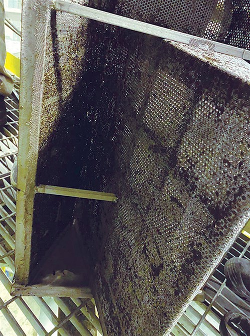 |
| FIG. 4. Dirt accumulation in pump strainers. |
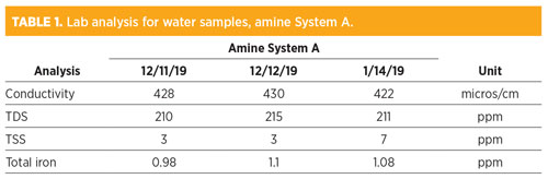
Lab analysis of water chemistry parameters (TABLE 1) from amine System A showed them becoming stable for at least four consecutive days through lab sampling, indicating that amine System A became cleaner.
 |
Amine System B. The system was placed under soft startup on December 4, 2019, and in cold circulation until December 13, 2019. During the cold circulation phase, two of the lean amine cooler bays (50%) were isolated and amine was run through the other two bays to increase turbulence and ensure cleanliness. After the system was stabilized and the in-service bays were deemed clean, the bays were isolated and the other two bays were put in service. The switching practice continued until consistent readings on the pump strainers were achieved. Following that process, amine System B was placed in hot circulation (FIG. 5).
 |
| FIG. 5. Cleaning frequency for amine System B. |
Fin fan tubes were cleaned by limiting the flow to two bays at a time, which allowed turbulence flow across the fin fan tubes. During this process—as with System A—a sudden increase in deferential pressure was noticed in all pump strainers due to dirt accumulation.
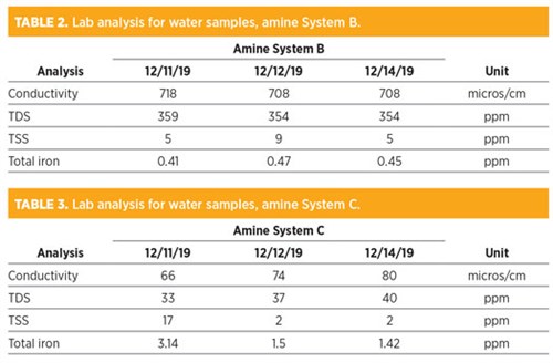
Lab analysis of water chemistry parameters from amine System B (TABLE 2) showed them becoming stable for at least four consecutive days through lab sampling, indicating that amine System B became cleaner.
 |
Amine System C. The system was placed under soft startup on December 10, 2019, and in cold circulation until December 13, 2019. The system was then placed in hot circulation. During the water circulation phase, the amine System C circulation pump strainers were cleaned frequently. The cleaning practice continued until the system become clean.
Lab analysis of water chemistry parameters from amine System C (TABLE 3) showed them becoming stable for at least four consecutive days through lab sampling, indicating that amine System C became cleaner.
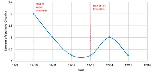 |
| FIG. 6. Frequent strainer cleaning for amine System C. |
Takeaway. Based on results from experimental runs on three units, the soft startup concept has proven advantageous, helping avoid common commissioning challenges of a new amine system (e.g., gas treatment facility)—including foaming, the presence of unwanted debris or materials in piping and vessels, etc.—and ensuring the short- and long-term reliability of an amine system facility. GP
 |
AYIDH AL-QAHTANI is a team-oriented Process Engineer with demonstrated experience in technical services for Saudi Aramco. He is a chemical engineer with 6 yr of experience in engineering services and technical support. During his filed assessment, he worked in gas plant facilities including, but not limited to, acid gas removal, dehydration and sulfur recovery. He has been involved in operations, process and technical support and led gas plant startups from pre-commissioning to gas production of gas sweetening units. Mr. Al-Qahtani holds a fundamental engineering certificate.
 |
ABDULLAH AL-WARTHAN is a Process Engineer at Saudi Aramco with demonstrated experience in upstream operations. He has 8 yr of experience in gas operation fields as he led the commissioning of the gas treat unit in one of Saudi Aramco’s main facilities (Fadhili Gas Plant). Prior to that, he was assigned as a Lead Process Engineer at the Khursaniyah Gas Plant. Mr. Al-Warthan holds an energy auditor certificate.
MMAJED AL-SUBAIE is a Process Engineer at Saudi Aramco with demonstrated experience in upstream operations. He has 7 yr of experience in gas operation fields as he led the commissioning of the gas treat unit in one of Saudi Aramco’s main facilities (Fadhili Gas Plant). Prior to that, he was assigned as a Lead Process Engineer at the Shaybah Gas Plant. Mr. Al-Subaie holds professional engineering, energy manager and energy auditor certificates.


Comments