
Feed gas quality limits acid gas removal unit capacity
Plant A is a gas processing and natural gas liquids (NGL) recovery facility designed to process 2.53 Bsft3d of sour associated gas received from four segregated gasoil separation plants (GOSPs). The separated gas is a mixture of solution gas (originally in crude) and cap gas (present in an upper dome over the crude and representing more than 60% of the separated associated gas from the GOSPs).
The sour gas is processed for NGL recovery, and some 1.5 Bsft3d of residue gas is recycled back to the GOSPs for reinjection. 260 MMbpd of C2+ NGL is sent to Saudi Aramco’s downstream facility through pipelines for further processing. Plant A consists of the following main process areas (FIG. 1 shows an overall process description):
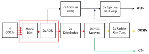 |
| FIG. 1. Overall process description. |
- Inlet facility
- Acid gas removal units (AGRUs)
- Molecular sieve dehydration units
- NGL recovery units
- Acid gas compression
- Reside gas compression
- Injection gas compression.
Sour feed gas streams from the GOSPs combine in a common manifold and enter the Plant A inlet area, which consists of three parallel slug catchers with a capacity of 950 MMsft3d each. These slug catchers were designed as a three-phase separator to handle the slug during the pipeline scrapping operation and to separate the accumulated water and hydrocarbon liquids from the sour gas. According to the original design of the gas plant, no free liquid was anticipated during normal operation.
Sour gas from the slug catchers is joined again through a common manifold before it splits into two streams to feed the two identical AGRUs, which have a capacity of 1.253 Bsft3d each. The AGRU uses formulated methyl diethanolamine (MDEA) with piperzine (PZ) (50 wt% MDEA, 4 wt% PZ and 46 wt% water) to achieve a sweet gas specification of 4 ppmv hydrogen sulfide (H2S) and 50 ppmv carbon dioxide (CO2).
Sour gas is fed to the amine contactor where treated sweet gas is routed to the NGL recovery units for further processing. The rich amine is sent to the amine regenerator where acid gas is stripped off and sent to acid gas compressors for reinjection into the reservoir. The regenerated lean amine is recycled back and cooled by fin-fan coolers before it enters the top section of the amine contactor to remove acid gas from the feed sour gas.
Since its startup, Plant A experienced unstable feed gas quality that consequently impacted plant sustainability and resulted in capacity limitations and frequent foaming incidents. An engineering team performed extensive troubleshooting and investigation efforts to address these challenges, along with an action plan to mitigate the impact. The plant evaluation revealed that unit capacity limitation was mainly caused by increased acid gas content (H2S and CO2) in the feed sour gas by more than 50%. The presence of heavy hydrocarbons in the feed sour gas contributed to the foaming incidents in the acid gas absorber. Foaming resulted in excessive amine losses and off-specification product gas, as well as sudden reductions of feed gas flows. The issue was more severe during summer, when the unit experienced several incidents of foaming on a weekly basis. The impact resulted in more than a 50% reduction in plant processing capacity on a temporary basis.
Methodology and study basis. The comprehensive engineering efforts to evaluate and troubleshoot the capacity limitation of Plant A considered the following during the assessment:
- Review of the plant design, including the basis of design and original simulations.
- Review of the inlet area, AGRU and upstream GOSPs operation, which included main parameters changes, equipment failure and main streams conditions.
- Process data from the inlet area, AGRU and upstream GOSPs. This included historical process input and trends, operations records, routine/non-routine streams analyses, and visual inspection of main equipment in the field during operation.
- Collecting different gas and amine samples and performing simulation based on design and actual data.
FINDINGS AND ANALYSIS
Plant design and simulation. A thorough review of Plant A design revealed the following:
- The field has cap gas that represents more than 60% of the produced gas at the GOSPs. This cap gas is mixed with the crude inside the reservoir. During plant design, the GOSPs were simulated based on crude oil samples representing the north and south part of the field; however, only the cap gas composition for the south field was used. This resulted in lower acidity in the final simulation. Late samples revealed that the north field cap gas has a higher acid gas content; therefore, it has a major impact on produced gas acidity.
- The compositions and flowrates of the gas produced from the GOSPs are not identical. To some extent, more gas is produced from the north field (hence the higher acid gas content).
- The gas simulation of the GOSPs without the north field cap gas data resulted in low acid gas content (1.2 mol%–1.4 mol%) in the GOSPs’ associated gas. However, when the north field (higher acid gas content) data was used, the acid gas content in the GOSPs’ associated gas increased to 2.1 mol%.
Upstream GOSPs and inlet area. Based on the team assessment of upstream units operation (GOSPs, inlet area and feed gas filter-separators), the main findings included:
- Normal operation at all GOSPs. Several factors contributed to periods with unexpected gas compressors shutdowns; however, no direct impact on the downstream facility could be noticed. The number of shutdowns was significantly reduced later.
- Steady operation of the triethylene glycol (TEG) dehydration unit. The four GOSPs are comprised of nine upstream TEG units. Their operation was steady except for one of the units, where low performance was noticed—this was due to operational issues in the TEG regeneration section. The impact of this will be related to water carryover with the gas, which has no direct contribution to foaming. The subject TEG unit performance was significantly improved later. The TEG units were excluded as a direct cause of the foaming issue.
- High operating temperature of the TEG units at the GOSPs. The GOSPs area experiences high ambient temperature during summer: it is difficult to cool the associated gas and maximize heavy ends condensation. This results in intermittent TEG carryover and high hydrocarbon dewpoint of the produced gas. The original facility was designed in the 1990s without NGL recovery, so no refrigeration unit was built. NGL recovery was introduced in 2015, so it was infeasible to install refrigeration units at the GOSPs.
- High acid gas and C6+ content. Many gas samples during summer and winter were collected from the outlet of the four GOSPs, the inlets to the Plant A slug catchers and the inlets to the two AGRUs. All samples confirmed high acid gas content of 1.8 mol%–2.1 mol% of acid gas (H2S and CO2) and slightly higher C6+ levels of 0.7 mol%
The presence of hydrocarbons in AGRU equipment. The pure amine solution does not foam easily, but foaming can be initiated by many factors, such as hydrocarbon liquid, corrosion inhibitor and amine degradation products. Plant A experienced several foaming events at different intervals in the amine contactors in both AGR trains. The foaming resulted in excessive amine losses and off-specification product gas, in addition to sudden reductions of feed gas flows. Frequent liquid hydrocarbon accumulation occurred in the amine contactor at both AGR trains. At peak times, the Plant A operation team drained the amine contactor several times per day to skim the liquid hydrocarbon that was accumulating in the system.
During the summer of 2017, numerous foaming incidents took place, so the team investigated the amine contactor and flash drum operations. It was confirmed that there was significant liquid hydrocarbon carryover to the AGRU unit. This was proven through:
- Visual inspection of the equipment sight glass, which showed a significant layer of hydrocarbons (FIG. 2)
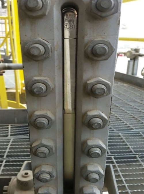
FIG. 2. Hydrocarbon layer in an amine contactor. - Excessive skimming of both the amine contactor and flash drum, multiple times a day
- Amine samples collected that showed the presence of hydrocarbons in lean amine solution.
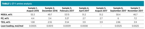
Amine solvent quality. Monitoring the amine solvent quality is crucial to assess the AGR unit performance. The Plant A lab and several third-party labs analyzed the lean amine solution quality for both AGR trains. TABLES 1 and 2 show the analyses results:
 |
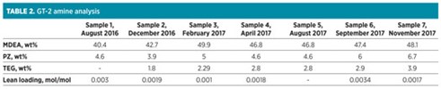 |
- H2S and CO2 in the lean amine for both trains are below the recommended range of 0.0005 mol/mol–0.003 mol/mol, which indicates over-stripping of rich amine. The presence of H2S at low levels (typically 300 ppmv) is important to provide an iron sulfide protection layer against corrosion.
- The samples showed that amine solvent concentration (MDEA + PZ) is within the recommended range of 50 wt%–57 wt%.
- All analyses results showed TEG content in the amine samples, the impact of which is discussed here.
TEG contamination in the amine solvent loop has a negative impact on the gas treat unit capacity, as it can replace the active amine. The GOSPs TEG systems are designed to dehydrate the sour gas and remove the water content below 7 lb/MMsft3 to protect the pipelines from water condensation. The TEG contactor is operating at 140°F, where the expected TEG vaporization losses are relatively high.
High acid gas contents in feed gas. The authors’ company’s lab and a third-party vendor lab conducted extensive work to perform complete analysis of the sour gas from the four GOSPs plant outlet and the Plant A inlet. The measurements were conducted between November 2016 and October 2017. In addition, a plant simulation was performed using crude and gas samples representing the whole field (north and south sections) to verify and compare with actual measurements. The simulation results were validated by the field sample analysis. The following were practiced during field sampling:
- Samples were collected from four GOSPs outlets and the two AGRU inlet headers
- Two samples per day representing day and night conditions were collected for each location
- Samples were collected for at least one week. More than 100 samples were collected in total, representing summer/winter and day/night compositions of the sour gas.
Based on the samples analyses and actual simulation of GOSPs operation using the updated compositions:
- The measurements and simulations confirmed a significant increase of acid gas content in the feed gas stream (FIG. 3) from the design of 1.21 mol% to 1.8 mol%–2.1 mol%.
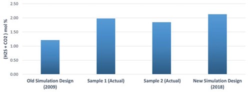
FIG. 3. Acid gas content in feed gas. - The C6+ hydrocarbon increased from 0.68 mol%–0.71 mol%.
- A significant BTEX (benzene, toluene, ethylbenzene and xylene) of more than 1,000 ppm was measured. The BTEX measurement was not a typical analysis during the design phase, therefore it was not considered. BTEX has a significant impact on promoting foaming in the amine contactor. Although the unit is operating at a relatively high temperature (140°F–145°F), which reduces BTEX absorption, the solvent-rich loading is relatively low (0.2 mol/mol–0.25 mol/mol), which promotes BTEX absorption.
Since the AGRU was designed for 1.21% mole acid gas (equivalent to 37 MMsft3d acid gas volume), the new acid gas content of 1.8%–2.1% limits the plant processing capacity to less than 1.8 Bsft3d, which is a reduction of more than 600 MMsft3 of processing capacity.
The main conclusions from the study are:
- The plant feed gas composition that was used to design the AGRU did not represent the actual composition of the feed gas to the plant—mainly the acid gas content and heavy C6+ components, which had significant impact on AGRU capacity. The actual sour feed gas acid content is more than 50% compared to the original design.
- Heavy hydrocarbons frequently collected inside the AGRU amine contactor. These hydrocarbons were the main cause for the frequent foaming in the unit.
- The topography of the plant area resulted in unstable feed conditions (temperature and liquid carryover) to the plant. Diurnal impact was evident were the feed gas temperature fluctuated significantly between day and night, especially from nearby GOSPs (2 and 3)
- The oil field has unique characteristics: the south part cap gas contains less acid gas (~ 1 mol%), while the north section of the field has more acid gas in the cap gas (~ 2.3 mol%). This resulted in a major discrepancy between the actual feed gas composition and the original composition that was used during the design.
- The inlet gas temperature was too high and resulted in lower amine capacity and, consequently, limited the AGRU from accommodating higher feed gas.
- The current piperazine concentration of 4 wt% contributed to the limited amine capacity to process additional acid gas.
- The upstream equipment was inefficient in removing entrained liquids. The inlet slug catchers did not have internals to reduce liquid carryover, and the inlet feed gas filter separator size was inadequate to handle the design flowrate at actual conditions.
RECOMMENDATIONS
Install a dewpoint control unit (DPCU) upstream of the AGRU. The DPCU will eliminate the impact of fluctuating sour feed gas conditions (liquid carryover, temperature and composition). It will ensure stable and lower feed temperature to the AGRU, remove heavy hydrocarbons, significantly improving the performance of the AGRU and enable the unit to process more sour gas. The design of the DPCU considers multiple raw crude and gas cap samples representing the field.
The raw data is used to develop a new simulation of the plant based on the latest crude oil and cap gas composition, representing the north and south part of the field to design the new DPCU and debottleneck the current AGRU capacity limitation.
Although this option will imply capital investment, it is the ultimate solution to resolve the frequent foaming and limited AGRU capacity. It is critical to consider such an option at the early stage of plant design, bearing in mind all factors that affect the decision (i.e., actual gas hydrocarbon dewpoint temperature, content of C6+, ambient conditions, length and size of feed gas pipelines).
The new simulation results and actual gas composition measurements will be used as the basis for any new plant modification and DPCU design (FIG. 4).
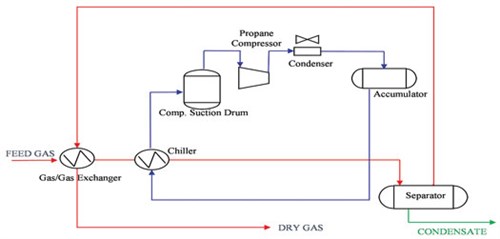 |
| FIG. 4. Schematic of the proposed dewpoint control unit. |
Increase piperazine concentration. The increase of piperazine concentration will result in higher capacity (pickup ratio) and a lower contactor temperature in active trays, which will further increase unit processing capacity. In this case, the lower design piperazine concentration provided the flexibility to increase the concentration to support higher amine loading.
This proposal was simulated using process simulation softwarea, and the new temperature profile showed that acid gas absorption is enhanced, which will allow the amine contactor (FIG. 5) to accommodate more acid gas content (a 4°F reduction in bulge temperature was realized).
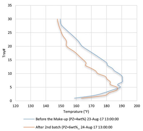 |
| FIG. 5. Amine contactor temperature profile for GT#1. |
Modify the slug catcher internal. The three slug catchers are the first protection layer to remove the heavy hydrocarbon from the associated gas fed via pipelines. The existing slug catchers were provided with conventional demister mesh pads, which proved to be inefficient and resulted in a significant amount of liquid hydrocarbon and water carryover with the gas stream to the amine unit. The situation was aggravated under the several operating scenarios, such as occasional slug flow regimes (scrapping, startup/ shutdown), solids entailment in the feed gas and defective level controls. Therefore, it was proposed to modify the slug catcher internal to improve gas distribution, improve solid removal, enhance residence time, improve gas-liquid separation and minimize carryover to less than 0.1 gal/MMsft3.
Install a gas-liquid coalescer. The feed gas filter-coalescer is an essential piece of equipment in the AGRU, as it protects the amine unit from any liquid carryover. Typically, the system should be designed with the highest removal rate (99.9% solid removal and maximum of 0.1 ppmv liquid in the gas outlet). Since the existing filter-separator is under-sized, a new filter-coalescer was recommended. An alternative is to upgrade the existing one through the use of different coalescing elements. The new conditions after installing the dewpoint control will determine the need to replace or upgrade the existing system.
Use alternative anti-foam agent. The current anti-foam that is used at Plant A is silicone-based. During foaming upsets, batch injection (concentrated anti-foam) is applied. The excessive use of this type has a potential to create operational issues, such as accumulation in the system, which could reduce amine capacity and block equipment like the lean rich exchanger.
It was recommended to consider other types with less potential impact, such as glycol-based. The appropriate type should go through laboratory testing to ensure effectiveness, compatibility and minimum long-term effect.
A new type of anti-foam was implemented and based on the continuous monitoring of the main foaming related parameters of the AGRU, the units’ foaming tendency was significantly reduced and the number of foaming incidents decreased. GP
NOTES
a ProMax
 |
SAUD MUDAIBEGH is a Process Engineering Consultant working for Saudi Aramco. He joined the company in 1995 and is part of the Upstream Process Engineering Division. He worked in the Uthmaniyah Gas Plant for 3 yr as an Operation Engineer. Mr. Mudaibegh has 25 yr of experience in oil and gas processing with a focus on gas sweetening, dehydration, NGL recovery, and modular process units design and fabrication. He graduated from King Fahd University of Petroleum and Minerals with a BS degree in chemical engineering. He is also the Chairman of Oil and Gas Process Engineering Committee for Saudi Aramco.
 |
MESHAL AL-HARBI is a Process Engineer working for Saudi Aramco since 2012. He is part of the Process and Control Systems Department/Gas Processing Group. Mr. Al-Harbi worked in the Khursaniyah Gas Plant for 3 yr as an Area Operation Engineer, where he gained extensive experience in several systems: acid gas removal, acid gas enrichment, gas/liquid dehydration, mercury removal, propane refrigeration, condensate stabilization and NGL recovery unit. He also worked for 2 yr as a Project Engineer in the Hawiyah Unayzah Gas Reservoir Storage. Mr. Al-Harbi graduated from King Fahd University of Petroleum and Minerals in 2012 with a BS degree in chemical engineering.
 |
MUHAMMAD RIZWAN TARIQ is a Senior Process Engineer within the Process & Control Systems Department for Saudi Aramco. He has also served as Staff/Senior Engineer at JGC Japan, Worley Oman, PDO Oman and OGDCL Pakistan. Mr. Tariq has 20 yr of experience in oil and gas processing with a focus on gas and liquid sweetening, dehydration, LPG recovery, condensate stabilization and sour water stripper. He holds a BS degree in chemical engineering from Punjab University Lahore Pakistan. He is a chartered member of IChemE and the Engineering Council UK and a Professional Engineer from PEC Pakistan. The author can be reached at muhammad.tariq.1@aramco.com.


Comments