
Optimize the design and configuration of ambient air heaters for LNG regasification
An LNG regasification terminal converts LNG from a temperature of nearly −160°C back into natural gas at atmospheric temperature for distribution across a consumer network. The regasification of LNG is generally conducted using one of the following types of vaporizers: an open-rack vaporizer, a submerged combustion vaporizer, an ambient air vaporizer or an intermediate fluid vaporizer.
The selection of vaporization technologies for a regasification terminal is determined by CAPEX, OPEX and associated environmental issues at the site. Looking at these aspects, a distinctive trend is the use of a shell-and-tube vaporizer (STV) with a closed-loop intermediate fluid and ambient air as the heat source. The intermediate fluid may be a glycol, a glycol-water mixture, methanol, propanol, propane, butane, ammonia or formate. This intermediate fluid vaporizes LNG in the STV, and the cooled intermediate fluid is sent to an ambient air heater (AAH), where it regains the required heat from ambient air and then returns back to the STV, forming a closed loop. FIG. 1 shows a typical process flow diagram for an LNG regasification terminal with an STV with a glycol-water mixture as the intermediate fluid and an AAH as the primary heat source.
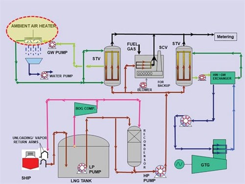 |
| FIG 1. Typical process flow diagram for an LNG regasification terminal with an STV. |
Regas vaporizer and heater structure. In general, an LNG regasification terminal with a capacity of 5 MMtpy that uses an ethylene glycol-water mixture (36 wt%) requires four parallel working units of STVs and AAHs. Each AAH has approximately 24 bays, 48 tube bundles and a design heat duty of 36 MW. A considerably large plot area (around 7,600 m2) is required for the installation of the AAHs. The number of units can vary, depending on the size of the STV. Using a larger-size STV may require fewer units.
An AAH looks similar to a conventional air-cooled heat exchanger (ACHE), which is widely used in refineries and other industries; however, the purpose of an AAH in LNG regasification terminals is the opposite—i.e., instead of cooling the hot process fluid by atmospheric air, the AAH heats the colder intermediate fluid coming from the STV by using the comparatively hot ambient air. FIG. 2 shows a typical AAH installation in an LNG regasification terminal.
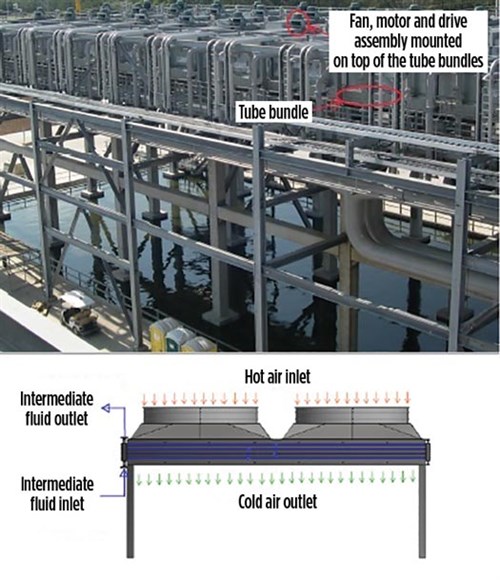 |
| FIG. 2. Typical AAH installation in an LNG regasification terminal. |
Challenges to heater design. An AAH presents challenges related to thermal design, construction and operation compared to the conventional ACHE. The following sections discuss those challenges in detail, along with recommended solutions that have been successfully implemented in many LNG regasification terminals.
Temperature and humidity. Atmospheric temperature and relative humidity (RH) at any location fluctuates within a day and throughout the year; they also fluctuate within an LNG regasification terminal. Varying atmospheric temperature and RH influence the performance of an AAH. Therefore, it is crucial for a process engineer to carefully analyze past meteorological site data while determining operating scenarios or cases for designing the AAH. A minimum approach temperature (i.e., the difference between the inlet temperature of ambient air and the outlet temperature of the intermediate fluid) of 3°C–4°C is recommended to achieve an economical and efficient AAH design.
The AAH performs at maximum capacity during higher atmospheric temperatures, and some of the fans forcing air into the AAH may be required to switch off. However, it is recommended to use variable frequency drives for at least 50% of the total number of fans and motors to ensure effective process control and maximum electrical power savings in the AAH.
During lower atmospheric temperatures, water vapor present in ambient air commonly becomes condensed when passing through the tube bundles due to the transfer of heat to the intermediate fluid flowing inside the tube bundles. This condensed water vapor tends to slide down to grade by its gravity.
Condensed water and fan issues. As shown in FIG. 2, it is recommended to force the air into the tube bundles from the top by forced-draft fans and install the complete drive assembly (including fans, motors and a belt drive) at the top of the tube bundles to avoid rust, corrosion and damage. This recommended arrangement also helps minimize departed cold air recirculation, discussed later in this article. It is important to mention that a good amount of condensed water is collected at grade below the AAH, which must be suitably utilized.
While fans are located at the top of the tube bundles and force air from top to bottom, it is recommended to flow the intermediate fluid from bottom to top inside the tube bundles. Therefore, the inlet nozzles for the intermediate fluid should be located at the bottom of the tube bundles and the outlet nozzles should be located at the top of tube bundles, as shown in FIG. 2. This way, a counter-current to crossflow arrangement is achieved between the two fluids, which improves the logarithmic mean temperature difference (LMTD) and the heat transfer coefficient, therefore improving the thermal performance of the AAH.
Due to the condensation of water vapor present in ambient air, substantial fog and mist is generated below the tube bundles and around the AAH. This phenomenon becomes more significant when the unit is operating during lower ambient temperatures, high humidity and low wind conditions.
With the given AAH layout, site meteorological data (e.g., prevailing wind direction and wind velocity) and wind obstructions (e.g., surrounding tall structures, LNG tanks, buildings, etc.), it is recommended to carry out a computational fluid dynamics (CFD) analysis for the AAH to predict air stream behavior. Based on this CFD analysis, a suitable elevation and appropriate layout for the AAH should be selected so that the surrounding hot atmospheric air can mix with the exiting cold air from the AAH to considerably reduce fogging. However, a higher elevation can result in the carryover of condensed water with wind, which must be prevented by a condensed water removal system.
Cold air recirculation. Some amount of cold air exiting the AAH recirculates back to the fan suction at the top of the tube bundle (i.e., cold air recirculation). This further reduces the temperature of air entering the AAH, which can impact the overall performance of the AAH. As previously recommended, a CFD analysis is essential to accurately estimate the occurrence of cold air recirculation and its impact on suction air temperature. Based on the results of this analysis, necessary corrections to the design air temperature or implementation of adequate overdesign margins must be taken into consideration for the design of the AAH.
Detailed investigations that have been carried out at various LNG regasification terminals reveal that cold air recirculation cannot be fully avoided, but its effect can be minimized by selecting a suitable elevation and proper layout for the AAH. As shown in FIG. 3, a parallel installation for the AAH is more susceptible to cold air recirculation than AAH installation in series. This is because cold air recirculation is mainly caused by the confluence of air streams coming from the parallel units. Hence, the simplest and most efficient solution for minimizing cold air recirculation is to install AAHs in series.
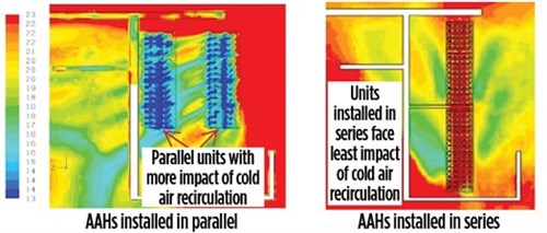 |
| FIG. 3. Parallel installation for the AAH is more susceptible to cold air recirculation than AAH installation in series. |
Latent heat considerations. The most important aspect in the optimization of the thermal design of AAHs is to consider the latent heat released by the condensed water vapor. The amount of condensed water depends on the site-specific relative humidity and dewpoint temperature. The latent heat of the condensation of water is substantially higher than the heat of air. Considering a higher relative humidity in design, the size and cost of the AAH can be considerably reduced; alternatively, a low relative humidity can increase the size and cost of the AAH. In light of this, a process engineer must carefully determine the design relative humidity prior to planning.
Note: The boundary layer of condensed water vapor that forms on the tube and fin surfaces acts as a resistance to the heat transfer from air to the intermediate fluid, which must be taken into consideration in the thermal design of the AAH.
Fin spacing in tubes. Fin spacing in the finned tubes of the AAH must be suitably selected to enable the easy release of condensed water from the tube and fin surfaces. Closely spaced fins may create resistance in the release of condensed water and may also lead to the formation of a thick boundary layer on the fin and tube surfaces, creating resistance to heat transfer. As shown in FIG. 4, it is recommended to establish a minimum fin spacing of 2.54 mm for extruded aluminium fins, which enables sound mechanical bonding with base tubes and efficient heat transfer.
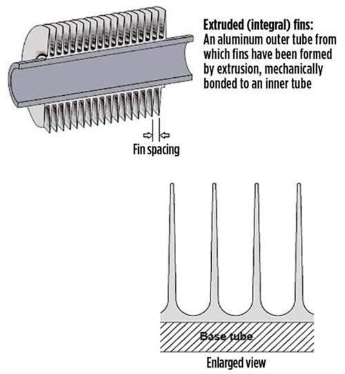 |
| FIG. 4. Recommended minimum fin spacing to enable the release of condensed water from tube and fin surfaces on the AAH. |
A higher number of finned tube rows in the AAH is to be avoided. Four finned tube rows are ideal for the easy release of condensed water in both high-humidity and relatively colder sites. In the case of limited available plot area, one or two additional tube rows can be used, preferably with higher fin spacing or without fins and a higher tube pitch.
Maintenance. Provisions for the maintenance of fans, motors and drive assembly mounted at the top of the tube bundles should be provided.
Support structures. Tube bundles for ambient air heaters are generally installed at an elevation of 10 m–13 m. Since water condensation routinely takes place, a supporting structure of concrete can be used for the AAH, instead of conventional hot-dip galvanized steel. In this case, the shop run-in test at the AAH supplier’s factory should be carried out with a dummy supporting structure.
Tube length. A longer tube length, a higher number of tube passes and the maximum utilization of allowable pressure drop are the key factors to achieving an optimized thermal design for an AAH. However, the selection of tube length must be aligned with market availability, the available plot area, the feasibility of finning and transportation limitations (if any).
Takeaway. LNG regasification technology, encompassing an intermediate fluid and ambient air as a primary source of heat, has witnessed several environmental, CAPEX and OPEX benefits compared to other technologies, especially for humid and warm locations. The design and configuration features of AAHs described in this article have already been implemented at various LNG regasification terminals, resulting in economical and optimized selection and trouble-free operation of the AAHs.
Selection of an intermediate fluid, operating cases, design ambient temperature, design relative humidity and dewpoint temperature are critical parameters for the sizing of AAHs. A CFD analysis that considers all consequential site meteorological data (e.g., prevailing wind direction, wind velocity and surrounding tall structures like LNG tanks, buildings) provides an accurate prediction of cold air recirculation. This prediction can be used to determine the necessary correction for design air temperature or adequate overdesign margins, suitable elevation and the most effective layout. An effective layout and suitable elevation also minimize the generation of fog due to condensed water vapor. GP


Comments