
Standardized, modular, small-scale LNG with low lifecycle cost
Natural gas has developed into the fossil fuel of choice for power generation, industrial use and domestic heating. It produces 30%–40% lower carbon emissions than oil or coal, and zero sulfur emissions. The capital cost of gas-fired power plants is half that of coal-fired facilities. For this reason, LNG is regarded as a high-growth market and is expected to become a low-carbon bridging fuel, pending full deployment of renewables and green or blue hydrogen-based fuels.
At present, the bulk of LNG is produced at low cost in large baseload plants with capacities of up to 7 MMtpy per train and having significant LNG storage facilities. After shipment, LNG is typically stored in a receiving terminal, regasified and used as fuel in power plants and gas grids. In addition to bulk supplies, LNG production plants and receiving terminals can provide competitively priced LNG to smaller markets within a reasonable distance by offering break-bulk volumes.
New LNG markets, including bunker fuel and transportation fuel applications, are developing fast due to environmental pressures around carbon dioxide (CO2), nitrous oxides (NOX) and sulfur (SOX) emissions. These markets are more distributed and often cannot be economically served by break-bulk volumes from existing LNG storage facilities. They are candidates for LNG sales from small-scale LNG liquefaction facilities operating on pipeline gas, flared gas, coal seam gas, biogas and small gas fields. However, these small-scale LNG plants face challenging economics given their small scale. Special emphasis must be placed on developing a competitive offering with the lowest lifecycle cost.
Achieving the lowest lifecycle cost requires:
- A process configuration that strikes a competitive balance between CAPEX and OPEX
- A project development and implementation approach that benefits from a lean, standardized, modular design; low-cost shop fabrication; and reduced project schedule.
This article describes an optimized solution to this challenge developed by the authors.
Process configuration. The selected process uses the feed natural gas in an optimized system of expanders to provide the necessary cryogenic refrigeration. As a result, no external refrigerants, such as nitrogen or mixed hydrocarbons, are required, with the following benefits:
- No requirement for refrigerant handling, storage, blending or transfer facilities, reducing the equipment count and capital cost
- No refrigerant make-up costs
- Reduced plot area
- High-efficiency process with low power demand
- Low power demand translates to low operating cost and low-cost compression equipment.
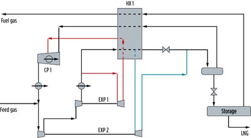
FIG. 1a shows the process flow scheme, which is suitable for a small-scale LNG plant with an output of up to 200,000 tpy.
 |
|
FIG. 1. Basic flow scheme of a small-scale LNG plant. |
A patented feature is that a partial liquefaction takes place in the low-temperature expander, EXP2. This very efficiently converts latent heat into mechanical work and reduces power demand by approximately 15%. It further reduces the size and cost of the main cryogenic exchanger, HX1.The concept is based on two expander circuits: a warmer circuit shown in red and a lower-temperature circuit shown in blue. The cold outlet streams from expanders EXP1 and EXP2 are routed to the cold box, HX1, to provide cryogenic cooling and are then returned to the expanders by the recycle compressor, CP1. The expanders are configured as expander-compressors, with the compressor sections in series with the primary compressor, CP1.
This process arrangement has been independently assessed as having a specific power demand 10% below that of single mixed-refrigerant processes and 25% below dual nitrogen expander processes.
To offer an overall optimized and integrated design, various feed gas scenarios have been developed, namely:
- Pipeline gas at pressure and containing low levels of impurities
- Low-pressure biogas or coal seam gas containing high amounts of CO2
- Low-pressure flare gas containing low levels of heavier hydrocarbons.
Optimized integration between the feed gas preparation and the liquefaction sections of the LNG plant is important to ensure high methane recovery and the lowest lifecycle operating cost for the overall facility.
FIG. 2b indicates typical feed preparation arrangements for a range of feed gas scenarios and how they can be integrated with the liquefaction section. It is necessary to remove CO2, water vapor and aromatics (benzene) to prevent freezing in the liquefier.
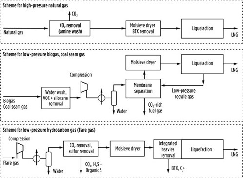 |
| FIG. 2. Three feed gas scenarios. |
The CO2 in natural gases, usually less than 5%, is conventionally removed by washing with amine. The gas is then dried with a molecular sieve. With high CO2 feeds such as biogas and coal seam gas, an arrangement of CO2 removal by membranes, followed by final CO2 removal and drying with molecular sieves, may be more suitable.
Aromatics in pipeline gas, typically below 100 mol ppm, are removed with molecular sieves or other sorbents. High concentrations of aromatics in the feed gas may be condensed, together with C5+, in the liquefaction section by an appropriate configuration of the warm expander circuit running through EXP1, with significant CAPEX savings over conventional NGL removal.
Project/product development and implementation. To develop a best-in-class, standardized and modular design,c innovative work processes have been applied, including:
- Structured lean design and development workshops with the entire design team, resulting in a capital-efficient design
- A proprietary, four-step project execution work processd was followed, comprising:
- Step 1: Identify factors that influence modularization
- Step 2: Determine degree of modularization and preassembly
- Step 3: Develop optimized layout
- Step 4: Develop modular support documentation.
Applying the aforementioned processes resulted in a design allowing 80% of the labor to be moved offsite compared to a traditional stickbuilt execution, as well as the ability to design one and build many plants.
The following sections provide more information on the concepts of lean design, standardization and modularization.
Lean design. Lean design principles were followed to develop a design that is the lowest lifecycle cost and provides the most competitive offering. This is illustrated in FIG. 3.
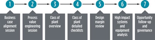 |
| FIG. 3. Lean design process and concept. |
Standardization. To offer a cost-competitive product, standardization was considered essential to reduce capital cost and the overall project schedule, as well as to reduce the lifecycle cost of the plants. Applying standardization supports the “design one, build many” philosophy and typically results in capital cost savings of 10%–20%, as illustrated in FIG. 4.
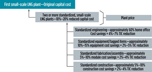 |
| FIG. 4. Standardization (“design one, build many”) concept. |
Modularization. The use of modules reduces onsite construction labor hours and allows for scalable, adaptable, plug-and-play units, as well as easy integration with existing systems. An added advantage is that the compact footprint optimizes the use of space. A compact modular solution also reduces capital cost due to improved labor productivity and reduced bulk material quantities.
Principles of modularization have been specified during plant development, including module definitions and basic layouts. A structured, four-step work process was applied in developing optimal modular layouts, with the aim of reducing the overall plot area and key quantities. The basic principle was to allow modularization to drive the layout, as opposed to the layout driving modularization.
For a 60,000-tpy, small-scale LNG plant, the most appropriate module transport envelope size was identified to be 14.6 ft wide × 14.6 ft high × 80 ft long. This transportation constraint fits most global inland transportation infrastructures, normally requiring only minimal permits. For smaller plant capacities, modules of 8 ft wide × 8 ft high × 40 ft long are being used, requiring no special permitting.
The modular layouts produce a percent modularization (amount of labor moved offsite compared to traditional stickbuilt designs) of approximately 75%–80%. FIG. 5 illustrates the conceptual layout for a 60,000-tpy, small-scale LNG plant and identifies the plug-and-play module definitions and numbering.
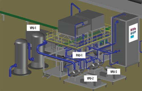 |
| FIG. 5. Breakdown and definition of a 60,000-tpy, small-scale LNG plant module. |
Modularization typically results in capital cost savings of 15% compared to a traditional stickbuilt execution. This number will vary in different locations depending on the craft labor cost and site productivity. An additional advantage of a modular plant is the ability to easily relocate the plant, if required.
Execution. Lean execution methods were used, including standardization and modularization, that provide program flexibility and scalability, cost and schedule certainty and overall schedule reductions. This section reviews the details on how this approach achieved a lean project execution.
Plug-and-play modules. The use of lean-designed, standardized, modular units allows for multiple plants to be built using standardized, plug-and-play process or utility modules. Each standard process module can be easily plugged in, depending on the operating requirements. For example, if local power is not available and electrical generation is required, then the appropriate electrical generator blocks can be plugged into the facility. Onsite LNG storage can be added by plugging in standard storage units. Utilities can be added by plugging in standard utility modules.
A limited number of standard-capacity module templates were developed within the small-scale LNG plant range, allowing for an optimal selection to suit a customer’s needs. Multiple modular trains can be installed to reach a desired overall output. An advantage of this approach is that additional trains can be added in a phased manner as the market is expanded, significantly reducing the initial capital cost and funding requirements.
Lean execution schedule. By applying a standardized design for a limited range of plant capacities, the overall execution schedule can be reduced by 40%–50% when compared to traditionally executed LNG facilities. A typical schedule would be 9 mos–12 mos from order to ready for commissioning, with modules being shipped to site ex-module yard within 6 mos–9 mos.
Commercial deployment. Commercial deployment of small-scale LNG plants is driven by four key factors:
- The need to reduce greenhouse gas emissions and decarbonize the energy industry
- The ability to supply gas competitively to users
- Alternative means of transporting gas to productive use
- Regulatory requirements.
The following section illustrates specific applications of small-scale LNG plants and highlights the economic viability of the opportunities.
Diesel fuel replacement. The use of LNG as a replacement fuel in diesel vehicles, trains, remote power stations or other industrial and heating applications presents an opportunity for small-scale LNG plants. The concept is based on extracting clean gas at pressure from gas distribution pipelines at various locations and the assumption that the LNG produced will be sold within a radius of 250 mi as a diesel replacement fuel. The opportunity is conditional on various factors, including the prevailing oil price and location of the point of use, and the location of a gas supply to feed the small-scale LNG plant. Even at relatively low oil prices, opportunities exist in land-locked countries with difficult or lengthy transportation logistics.
A case study of an optimized, 60,000-tpy, small-scale LNG plant using pipeline gas, as described in this article, is shown in FIG. 6. The figure illustrates expected returns against gas input price vs. LNG selling price. As an example, such a plant can achieve an internal rate of return of 25%, even at a $7/MMBtu gas input price, when delivering LNG to the customer at a price of $16/MMBtu.
 |
| FIG. 6. Typical return on investment for a generic, 60,000-tpy, small-scale LNG plant. |
With a diesel price of $3.16/gal ($22.80/MMBtu), this would reflect a direct fuel price reduction of around 30%. In addition, the efficiency of dual-fuel engines (LNG plus diesel) has, during field tests, been observed to be around 10% better than diesel only, resulting in additional savings for the end user. The actual cost savings and LNG plant netback price will depend on local and federal taxes and will be calculated more precisely for each specific opportunity.
Green renewable LNG from biogas. Biogas is obtained from the anaerobic digestion of domestic, industrial and agricultural waste and is typically reinjected to a gas grid or used to generate electricity. However, anaerobic digestion also presents opportunities for biogas liquefaction. In these cases, micro-scale LNG units of 5,000 tpy (or even smaller) may find application.
Harvested biogas is typically produced at atmospheric pressure and contains substantial quantities of water, N2 and CO2. It needs to be compressed and cleaned before being fed to the liquefaction section of an LNG plant. This results in higher capital and operating costs compared to pipeline gas but could still represent a profitable opportunity. FIG. 7 illustrates an expected return on investment for a 5,000-tpy bio-LNG plant.
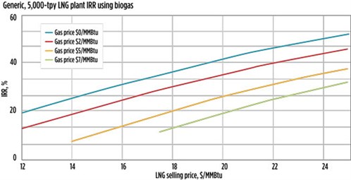 |
| FIG. 7. Expected return on investment for a generic, 5,000-tpy biogas-based plant. |
It is expected that a newly constructed biogas facility would need to sell the gas to a small-scale LNG plant at a price of around $7/MMBtu to recover its capital cost. This, in turn, requires an LNG selling price of at least $18/MMBtu—considerably higher than prevailing gas prices but potentially competitive against diesel or LPG. Furthermore, certain countries offer incentives to encourage the development of green renewable fuels, which considerably enhance the economic viability of such opportunities.
Flare gas recovery. Gas is flared from many gas fields and processing plants. The World Bank1 estimates from satellite data that, in 2019, flared volumes exceeded 5 Tft3 and that almost half of the total volume was generated in only four countries: Russia, Iraq, the U.S. and Iran. With the global move to net zero carbon, it would be surprising if these volumes were not targeted for recovery to beneficial use.
Flared gases are generally at atmospheric pressure and may contain quantities of heavier hydrocarbons. The gas must be compressed, and the heavier hydrocarbons recovered, before being fed to the liquefaction section of an LNG plant. The integrated heavies removal concept of the liquefaction process provides for the recovery of heavier hydrocarbons in a cost-effective way that could result in much-improved economics.
FIG. 8 illustrates the economics for a 20,000-tpy facility based on flare gas. This excludes the revenue from heavies recovery, which requires a case-by-case analysis that considers the gas composition, as well as the potential markets for the products.
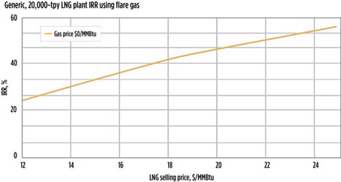 |
| FIG. 8. Example economics for a 20,000-tpy facility based on flare gas. |
Takeaway. Achieving economic viability for small-scale LNG applications is challenging, as they lack economy of scale relative to conventional LNG schemes. Applications are likely to be in the areas of liquid fuel substitution, locations where conventional fuel supplies are logistically difficult or where environmental pressures prevail.
Rigorous optimization from both a process design and detailed engineering perspective, along with the adoption of a lean, standardized, modular approach allow significant expansion of opportunities for small-scale LNG, to the benefit of gas owners and their fuel customers. GP
NOTES
a The dual methane expander process described in Fig. 1 is the ZR-LNG system (Zero Refrigerant LNG), which is owned, patented and licensed by Gasconsult Ltd.
b The Integrated Heavies Removal process shown in Fig. 2 is owned, patented and licensed by Gasconsult Ltd.
c The lean, standardized, modular, small-scale LNG plants described in this article are engineered and marketed by PolaireTecH.
d The proprietary, four-step work process used to optimize the lean, standardized, modular design is the Optimod Execution Work Process developed by DyCat Solutions Inc.
LITERATURE CITED
- World Bank, “Global gas flaring tracker report,” Global Gas Flaring Reduction Partnership, Washington, D.C., July 2020, online: https://pubdocs.worldbank.org/en/503141595343850009/WB-GGFR-Report-July2020.pdf
 |
FREEK VAN HEERDEN is Managing Director of PolaireTech. He graduated from Pretoria University in 1975 and joined AECI Limited in Sasolburg, South Africa as a Process Engineer. In 1998, he transferred to Sasol, an international petrochemical company, where he was involved in various coal and GTL, polymer, clean fuels and renewable energy projects globally as Engineering Manager and Technical Director. He was also a founding member of Owner Team Consultation, which assists owner organizations in the development of new projects. In 2019, PolaireTech was formed as a JV between Owner Team Consultation and Saiyl, an EPC company, to develop modular, small-scale LNG plant offerings.
 |
FRED HANEY is President of DyCat Solutions, a company that provides innovative solutions to the heavy industrial business sector. He is a recognized leader in developing the optimum capital efficiency for owners of heavy industrial projects. He has been globally recognized as a subject matter expert for his development of modular designs, practices and execution solutions. He is also the inventor of Fluor’s 3rd Gen Modular Execution.
 |
GEOFF SKINNER is Technical Director of Gasconsult. He graduated from Oxford University and joined Foster Wheeler in the UK in 1965. From 1981 to 1986, he was Technical Director of Foster Wheeler Synfuels Corp. in Livingston, New Jersey. On his return to the UK, Mr. Skinner acted as a consultant to several multinational companies and has registered a number of patents, including LNG and hydrogen liquefaction processes.


Comments