
Process technologies for LNG production
LNG is purified natural gas converted into liquid form. In this physical state, NGL takes up 1/600th the volume of gas in its natural form, making it economical to be stored in large-volume containers and transported over long distances via tanker.
The English scientist Michael Faraday first developed a way to liquefy methane in 1820. However, LNG first made its way to commercial application in 1959 when the first LNG tanker, the Methane Pioneer, sailed from Lake Charles, Louisiana, U.S. to Canvey Island, UK, where the government wanted to convert coal to natural gas following the Great Smog of 1952.
LNG international trade followed with LNG export from Algeria to the UK in 1964. Soon after, France imported LNG from Algeria, and Spain and Italy imported LNG from Libya. Today, the LNG industry has become the catalyst for the transformation of the global gas sector.
The LNG industry consists of three main processes: liquefaction and storage, ocean transportation via tankers, and storage and regasification. As an alternative to land-based projects, the liquefaction, storage and regasification steps can also take place on vessels, which include:
- FSRU: Floating storage and regasification units
- FLNG: Floating LNG vessels
- FPSO: Floating production, storage and offloading systems
- FPS: Floating production systems
- FSO: Floating storage and offloading systems
- FSU: Floating storage units.
In addition to the traditional uses of natural gas, and for its reduced environmental impact relative to coal and other fossil fuels, LNG has become popular as a clean energy vector in the maritime and transport sectors. This trend has also stirred interest in small-scale LNG plants.
Process technologies for LNG. Once natural gas has been pretreated to reduce the impurities to trace levels—i.e., water to 0.1 ppm, CO₂ to 50 ppm and Hg to less than 10 ng/Nm3—LNG is liquefied and subcooled by cooling the gas to –162°C (at 1 bar abs).
Natural gas liquefaction requires a significant amount of refrigeration. Since the adopted refrigeration cycles differentiate the commercial liquefaction processes, the most widely used refrigeration systems in the LNG industry are outlined in the subsequent sections, followed by the commonly used LNG production technologies.
Refrigeration cycles. The refrigerant fluid can be a single-component fluid (N₂, for instance) or a mixture of light hydrocarbons, generally termed as mixed refrigerant (MR).
In the latter case, the MR speciation can be varied to accommodate changes in the operating conditions. For example, in locations characterized by strong seasonal variations in ambient temperature, the MR composition is varied to accommodate these changes.
The selection of the refrigeration cycle is driven by the LNG production pattern. When the LNG is to be produced for peakshaving purposes, for example, the liquefaction plant does not operate on a continuous basis and the capacity is small. In these cases, the focus is on CAPEX rather than high efficiency, and the refrigeration cycle may be based on an inverted Brayton refrigeration (BR) cycle. In the BR cycle, refrigeration is supplied by expanding a single-component fluid (N₂) without fluid phase change. For medium to large production plants where high efficiency is important, a compression refrigeration cycle (CRC) with refrigerant phase change is used.
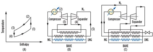
Inverted Brayton cycle. In the basic BR cycle, the cooling duty is provided by expanding nitrogen through a Joule–Thomson valve, or through an expander, without causing a change in the fluid state. The pressure of N₂ is raised from point (1) to point (2) and cooled at constant pressure to point (3) (FIG. 1A). In the following isentropic expansion to the pressure P4 < P3, the temperature ideally drops to T4, as per the formula shown in Eq. 1, providing the cooling stream against which natural gas can be cooled and liquefied:
 |
| FIG. 1. N₂ expansion refrigeration cycle. |
T4 = T3 × (P4 ÷ P3)^[(k – 1) ÷ k] < T3 (1)
Simplicity of design and ease of implementation are the main advantages offered by the BR cycle. However, since only sensible heat is transferred, the BR cycle may be economically advantageous only for micro- and small-scale LNG production, as increasing the cooling duty would result in an increase of N₂ flowrate and a disadvantageous increase in plant dimensions.
N₂ is not flammable, nontoxic, easy to procure and does not need storage facilities. For these characteristics, the BR cycle is often considered for offshore application where safety is a major issue. Moreover, it is not affected by wave-induced motion.
Compression refrigeration cycle. In the CRC, heat is extracted from a process stream by evaporating, at low pressure, the refrigerant fluid in a kettle-type heat exchanger and rejecting heat by condensing the refrigerant vapor at relatively high temperature.
The rejection is accomplished by transferring the extracted heat to an external utility or to a heat sink within the process, or to another refrigeration system (cascade refrigeration). The simplest refrigeration closed cycle entails a sequence of evaporation (heat extraction at low pressure), compression, condensation (heat rejection at high pressure) and expansion. “Closed cycle” means that the working fluid of the refrigeration system is permanently contained within the mechanical system.
In the context of the LNG industry, the thermodynamic efficiency of the basic closed cycle can be improved by increasing the number of refrigeration stages or by using more than a single working fluid (refrigerant) in a cascade arrangement.
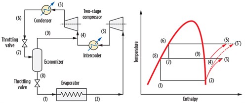
FIG. 2 shows a dual-compression, dual-expansion refrigeration system. The refrigerant vapor stream (5) at high pressure is cooled and expanded in a throttling valve. The resulting two-phase flow is separated in the economizer. The vapor is recycled back to the second stage of the compressor after having been mixed with the outlet stream from the compressor intercooler. The pressure of the liquid phase withdrawn from the economizer is reduced by means of a second throttling valve and sent to the evaporator, where it provides the refrigeration duty by evaporating at low pressure.
 |
| FIG. 2. The dual-compression, dual-expansion refrigeration cycle. |
The thermodynamic transformation taking place in this refrigeration cycle is illustrated in the right side of FIG. 2. The power required to transfer heat from the evaporator to the condenser is given by the enthalpy (H) difference between points (5) and (2). If the pressure were raised with only one compression stage, the final state of the gas would be in the position (5*). Since ΔH(5-2) is less than ΔH(5*-2), the power requirement of the two-stage compression is less than the power required by a single-stage compression system.
It should be noted that if the throttling valves are replaced with expanders, the efficiency of the refrigeration is further increased because the expansion across a process expander provides additional cooling and power recovery. In most LNG facilities, the precooling of natural gas is accomplished with a tri-stage propane refrigeration cycle.
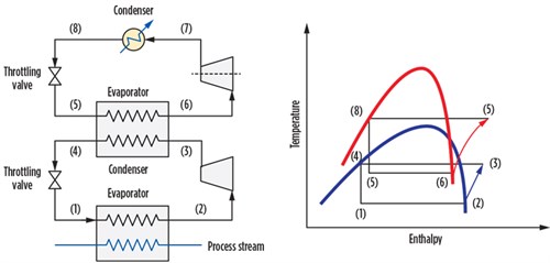
In the cascade arrangement, two or more refrigerant fluids (generally propane and ethane) are used in two distinct refrigeration cycles. The low-temperature cycle provides the cooling in the evaporator and rejects heat to the other cycle by means of the evaporator/condenser heat exchanger. This latter is common to both cycles. FIG. 3 illustrates the process setup for a cascade refrigeration cycle. The cascade refrigeration concept was used in early LNG plants.
 |
|
FIG. 3. Cascade refrigeration cycle. |
Mixed refrigerant. A single refrigerant fluid must be compressed and expanded to pressures low enough to reach a temperature colder than the process stream. The lower the gas liquefaction temperature, the larger its duty, and generally the more complex the refrigeration system becomes.
Since natural gas is a mixture of components, its condensation curve—the plot of temperature against specific enthalpy (J/kg) or cumulative heat rate—is a monotonic function that decreases over the entire enthalpy domain. An inherent loss of thermodynamic efficiency occurs when attempting to match the discrete single-refrigerant temperature levels with the condensation curve of process streams.
On the contrary, the boiling curve of a designed mixture of refrigeration fluid can better approach the natural gas cooling curve. In doing so, less external work is required for the liquefaction. MR used for liquefying natural gas generally contains methane (40%), ethane (48%), propane (9%) and nitrogen (3%). It should be emphasized that the actual MR speciation used in a specific plant depends on the natural gas composition and other project constrains, including environmental conditions.
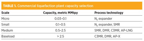
Production plants. The selection of a specific LNG production plant is driven by the feed composition, plant capacity, location, ambient conditions, safety and energy cost. As a short reference, TABLE 1 provides a list of the main commercial processes segmented according to plant capacity.
 |
Although comparatively less efficient, the N₂ recycle process and its modification account for a large share of production plants in operation today. The simplest system comprises a brazed aluminum plate-fin heat exchanger, a compressor and an expander, as shown in FIG. 1B. The circulating N₂ is compressed with a reciprocating, multistage compressor (for micro- and small-scale plants). The warm, compressed gas is cooled to 150K–175K by means of an external utility and auto-refrigeration (i.e., by heat transfer to the cold, low-pressure N₂ stream) and expanded in a Joule–Thomson throttling valve or through a gas expander.
The thermodynamic efficiency of this scheme is very low; the specific power required to liquefy natural gas can be greater than 1.5 kW/kg of produced LNG. The efficiency of this cycle can be improved by allowing the circulating gas to condense so that the latent heat of N₂ can provide part of the refrigeration duty. In this case, the basic N₂ recycle evolves into the process diagram shown in FIG. 1C.
Other modifications have been introduced to the basic scheme to improve the overall efficiency of the N₂ refrigeration system. One modification consists of expanding N₂ in three expanders, with each serving the cooling duty of an individual step (precooling, liquefaction and subcooling) of natural gas liquefaction, thereby achieving a split-pressure arrangement. Moreover, the multiple expansion allows for an increase in LNG capacity from 0.5 metric MMtpy to 1 metric MMtpy.
In a recent development, the efficiency is improved by combining an N₂ cycle with a CH4 cycle. The former cycle is for supplying precooling and liquefaction duty, while the latter is for subcooling the produced LNG.
Single mixed refrigerant (SMR). Further improvement of efficiency is attainable by replacing N₂ with an MR that has an adjustable composition to “simulate” the cooling of natural gas from ambient to cryogenic temperature. The SMR combines the simplicity of the plant configuration with operational flexibility while enhancing the overall plant efficiency by 10%–15% relative to the N₂ recycle plants.
In the baseload LNG industry, the most commonly used process configuration is a combination of propane precooled and mixed refrigeration (C3MR) processes. Generally, the propane cycle includes a three-stage refrigeration system where propane is boiled at three distinct temperature levels and the boiling curve forms three distinct steps.
Large production plants are arranged in multiple trains with parallel compressors and relevant drivers. The size of each train is increased to the maximum possible to pursue economies of scalea so that the unit cost—i.e., the CAPEX/t of produced LNG—is as low as possible.
Since a large flowrate of gas must be cooled from nearly ambient temperature to yield LNG at –162°C, the high heat transfer required entails a large heat transfer area. The heart of a baseload plant is the main heat exchanger (e.g., a spiral-wound heat exchanger, or SWHE). The SWHE consists of pressure vessels containing a number of tubing bundles fabricated with a large number of long, aluminum tubes helically wound around a mandrel or a central core. Numerous tube layers are formed in the radial direction. Each layer is separated from adjacent layers by spacers.
The SWHE comprises a warm exchange zone and a cold exchange zone. Together, the tubes clustered in the warm/cold zone constitute a single, coil-wound bundle. In the multi-tubes shown at the left of the warm zone in FIG. 4, the feed gas is cooled and partially condensed against a vaporizing refrigerant on the shell side of the bundle. The resulting two-phase flow is directed in the bundles of the cold zone, where it is further cooled and extracted as LNG.
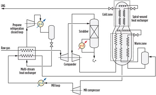 |
| FIG. 4. Propane-precooled SMR liquefaction technology. |
The refrigerant in the shell side is a mixture of light hydrocarbons. After being cooled and partially condensed in the MR refrigeration loop, the two-phase flow is separated in a knockout drum. The liquid from the knockout drum is subcooled in the tubes circuit, shown at the right of the warm bundle, and then throttled and mixed with the refrigerant flowing downward from the cold area. The MR flows downward over the outside of the spool bundle. By vaporizing and warming while flowing downward, the MR provides the refrigeration for cooling the feed gas and subcooling the liquid phase extracted from the knockout drum.
The refrigerant vapor from the knockout drum is cooled in the warm zone and passes through the tube circuit in the cold zone, wherein it is liquefied and possibly subcooled. After pressure reduction, it flows downward on the outer side of the spool bundle and evaporates, thereby providing the refrigeration duty to both the feed stream and the refrigerant vapor coming from the knockout drum. The refrigerant flowing downward in the SWHE becomes totally vaporized upon reaching the bottom.
The exchange configuration previously described is known as “top cold.” The opposite arrangement is “bottom cold.” In the latter configuration, LNG is withdrawn from the bottom rather than from the top.
Note: The vaporization of the MR fluid gradually flowing downward increases, and the heat transfer mechanism changes from two-phase boiling heat transfer at the top of the warm zone to single-phase vapor heat transfer at the bottom. However, the geometric data (e.g., coils diameter, tubes outside diameter, radial tubes spacing, tubes pitch and winding angle) are often kept constant throughout the bundle, meaning that the thermal design of these systems is the result of a tradeoff among the various heat transfer mechanisms.
Aluminum is the material of construction used for the SWHE and BAHE; therefore, a mercury removal unitb must be installed in the conditioning section of the processing facilities.
In a more recent enhancement, the C3MR has been integrated with an N₂ recycle refrigeration cycle in the rear end of the process. In doing so, the LNG subcooling duty is shifted from the cold zone of the SWHE to the N₂ recycle cycle, and the capacity of a single LNG train can be as much as 8 metric MMtpy–10 metric MMtpy, if the dimensions are left unchanged. This plant configuration licenses AP-X process technology.
In arctic regions, where the temperature can vary from –40°C to 30°C, the propane cycle becomes a bottleneck in the process because it is not possible to fully utilize the power from the compressor over the wide temperature range. In replacing the propane refrigeration cycle with an MR, the maximum utilization of power available from the compressor drivers can be attained while maintaining efficient refrigerant compressor operation over the wide temperature range. In these cases, the MR is constituted by a blend of ethane and propane. Increasing the proportion of propane creates a heavier mix suitable for summer operation, while increasing ethane yields a lighter mix for winter usage.
Dual mixed refrigerant (DMR). The process where the precooling duty is supplied by an MR heavier than that used for liquefaction and subcooling is known as dual MR (DMR). The DMR process provides the highest thermal efficiency in severe environmental conditions, but also the greatest equipment count, complexity and multiple refrigerant handling.
The cascade process is an alternative technology. In this process, natural gas precooling is carried out in an evaporator/condenser that is common to the high- and low-temperature refrigeration cycles. Since each refrigerant circuit is controlled separately, this technology does not need to adapt the refrigerant composition to natural gas. The most well-known commercial cascade process is ConocoPhillips’ Optimized Cascade LNG process. It cascades three pure refrigerants: propane, ethylene and methane.
It should be noted that plant components in cryogenic service are installed inside cold boxes. These boxes are created of a structural framework closed with steel plates, generally painted white, and filled with insulating material like perlite to avoid heat exchange with the surrounding environment.
Finally, the modularization concept is the emerging approach to economies of scale for baseload plants. Modularization entails multiple parallel, standardized, independent, small-scale LNG plants. In this way, new, identical production lines (modules) can be added as the market expands. This enables cost savings and capital budgeting over a longer span of time. GP
Notes
a By increasing the size of the plant, the CAPEX increases less than proportionally with the plant capacity (Q), according to the generally used estimate of 0.67. That is, CAPEX1 = CAPEX0 × (Q1/Q0) × 0.67, where CAPEX0 is the investment cost of a plant of capacity Q0 < Q1.
b This process was discussed in the Back to Basics article, “Natural gas phase separation and mercury removal,” published in the July/August 2020 issue of Gas Processing & LNG.
 |
LORENZO MICUCCI is a Senior Director at Siirtec Nigi SpA. He has more than 30 yr of experience in the engineering and contracting industry, most of which have been spent in the natural gas sector. In 2001, he joined Siirtec Nigi in Milan, where he directed the process design and operations department and the research and development department. During his time as R&D head, three patents have been granted to Siirtec Nigi, two of which have been implemented on an industrial scale. At present, he is the Senior Director of the technology and marketing departments. Mr. Micucci also worked for Saipem (Snamprogetti) as a Plant Designer for integrated gasification combined cycle and gas-to-liquids plants. He holds an MS degree in chemical engineering from the University of Bologna in Italy and is enrolled as a Qualified Engineer in the Register of Milan Order of Engineers.


Comments