
Natural gas pipeline systems and operations
Readers have demanded editorial content showcasing essential knowledge, common concepts and processes, and continuing education in the gas processing industry—and Gas Processing & LNG has responded. In the second of this teaching series of articles, the author explores the fundamentals of gas pipeline systems and operations. Keep an eye out for new “Back to Basics” articles in forthcoming issues of Gas Processing & LNG.
In the 4th century BC, Chinese historian Chang Qu described a strange “air of fire” used to light up rooms and to produce salt by boiling brine. Chang also reported an ingenious bamboo system sealed with bitumen, used to convey natural gas from a crack in the open countryside to villages; supposedly, he described the first known pipeline.
In 1859, American businessman Edwin “Colonel” Drake drilled a well of oil and associated gas near Titusville in Pennsylvania. The gas was delivered with a 2-in., 9-km-long pipeline to Titusville, mainly for lighting. Drake proved that natural gas could be transmitted safely and easily from its source to the marketplace, paving the way for the development of the natural gas industry.
Today, the total length of pipelines amounts to 2.76 MM km in more than 120 countries. In 2019 alone, pipeline projects were completed for a total mileage of 7,830 km, or about one-fifth of the earth’s circumference. These figures speak volumes about the importance of pipeline systems in the natural gas industry.
This article provides insights into the constitutive elements of pipeline systems. It also outlines technical issues related to the natural gas transmission and distribution sector and how seasonal demand variations are handled.
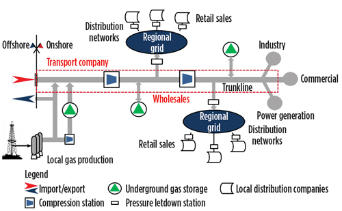
Trunkline and distribution networks. Pipeline systems are complex infrastructures connecting energy sources to end users, which are typically located far from delivery points. The delivery points generally correspond to metering stations at production facilities, where natural gas is transferred from producer to shipper, or the metering stations at the borders of importing countries.
A transport system contains transmission grids, or trunklines, along with a distribution network. A trunkline is a high-pressure (40 barg–80 barg for onshore, up to 200 barg for some offshore applications), large-diameter (20 in.–48 in.) pipe running a long distance, often on cross-border routes. It is designed to handle large volumes of gas received from a few entry points (gathering systems, central processing facilities and other receipt points). Generally, the exit points of a transmission grid are limited to laterals for connecting with regional (intrastate) networks, storage infrastructures and key consumer areas.
The distribution networks are intended to serve market areas. In general, this part of the system can be categorized as a regional distribution system operating at reduced pressure (20 barg–40 barg) to supply gas to industrial consumers, power plants and local distribution companies. It receives gas from trunklines or from local producers.
Local distribution networks receive natural gas from regional grids operating at a pressure of 5 barg–15 barg. This pressure is further reduced by local distribution companies to accommodate the requirements of end users. For example, gas is supplied to residential consumers at a pressure of 20 mbarg–40 mbarg.
Natural gas is a colorless and odorless commodity. To make leaks easily recognizable and mitigate the risks of toxicity and explosion, an odorizing compound is added to natural gas in the local distribution system. Tert-butyl mercaptan is the most used odorizing species; 10 mg/Sm3 will suffice.
Compressor stations. Natural gas flowing through transmission lines is subject to pressure losses due to friction. The resulting expansion of gas reduces the pipeline capacity, to the detriment of transport economy. Compression stations must be installed along the trunkline to limit the density excursion of the gas. As a rule of thumb, the maximum pressure drop allowed between two consecutive compression stations is approximately 25%–30% of the delivery pressure of the upstream stations.
A large compression station can include up to 12 compressors (centrifugal or reciprocating). These compressors are typically gas turbine-driven, with a power consumption of as much as 60 MW. The energy bill for natural gas transmission is an important account on the transport company’s financial statements.
The general configuration of a piping system is shown in Fig 1. Some large users are fed directly from the trunkline so that they can handle load transients. Indeed, the low pressure of a distribution network would not offer much storage capacity to rely on during transient conditions.
 |
|
Fig. 1. General pipeline system arrangement. |
Natural gas transmission pipeline systems are made of carbon steel having high yield strength and tensile strength. API 5L grade X65 and higher is the most popular carbon steel material used for high-pressure pipelines. For offshore applications, API 5L grade L450 is largely used. Distribution systems have been constructed from many different materials, including cast iron, steel, copper and plastic pipe. Plastic pipe is commonly installed today for gas distribution systems.
Dispatching centers. The points of entry, delivery and exit (including the in/out flows of storage systems), compression stations and maintenance activities must be carefully coordinated, monitored and controlled to ensure safe and efficient operations and to balance actual demand. Significant fluctuations in demand can be seen during the day and over weeks, as well as over seasons.
These activities are carried out through dispatching centers, which are based on telemetry networks, remote data transmission systems and centralized data acquisition monitoring, supervision and control systems. The heart of the dispatching center is a sophisticated software system—supervisory control and data acquisition, or SCADA. The SCADA system is capable of dealing with hundreds of thousands of pieces of data coming from a multitude of measurements in real time.
Pipeline design basics. A new natural gas market is built up from a limited customer base. A pipeline must be designed with respect to the dynamics of the markets to be served. It will require the optimum combination of piping diameters, compression stations and their distances in relation to the desired flexibility and expandability goals.
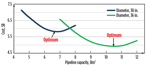
For a given pipeline diameter and length, the transport cost decreases with increasing capacity, since the CAPEX/capacity ratio decreases faster than the compression costs increase, as shown in Fig. 2. As capacity continues to grow, the slope of the curve decreases due to the more-than-proportional increase of the compression cost, which becomes prevalent to the right of the optimal point.
Different pipe diameters have different cost-capacity profiles; therefore, transport operators must select the optimal piping configuration in relation to the projected development of the market.
Fig. 2 also shows that pipelines can draw significant economy of scale: the optimum point decreases with increasing pipe diameter. For this reason, it is common practice to build a pipeline system with a larger pipe diameter than initially needed, but with the compressor capacity limited to current needs. New compressors can be added later, as the transport capacity demand increases.
 |
|
Fig. 2. Investment cost vs. pipeline capacity. |
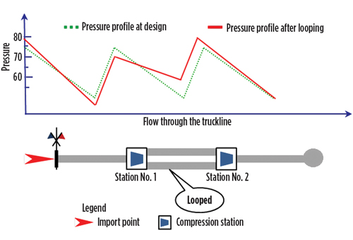
When the market grows beyond the optimal capacity, the transport operators first try to meet the extra demand by increasing the existing compressor delivery pressure, before investing in an expansion. However, this approach allows limited “wiggle room,” as the flow only increases with the square root of pressure drop along the line, while the energy consumption of compressors increases more than proportionally. After extracting the maximum extra capacity from the existing piping configuration, new market demand can be met by alternating the looping of an existing line with the addition of new compression stations.
Looping is when one pipeline is laid parallel between two compressor stations, creating two lines from one, as shown in Fig. 3. For a given capacity, the pressure drop between two consecutive stations of a looped system becomes one-fourth relative to a single line. The compression station to the right of a looped section can raise the pressure to the value corresponding to the augmented capacity, while maintaining the desired exit point pressure. The looping approach allows the capacity of the piping system to be augmented.
 |
|
Fig. 3. Pipeline looping. |
The distance between two compression stations ranges from 100 km–200 km. Looped pipes may extend the distance between compressor stations. Sometimes, the looping is used to create storage capacity, where natural gas can be line-packed as a way to increase deliveries to local customers during peak periods. In addition to delivery pressure modulation and looping, another option for expanding pipeline capacity is the installation of a new compression facility.
Submarine pipelines. In offshore gas exploration and production, submarine pipelines are used to connect platforms to the mainland. These pipelines are generally manufactured from composite materials. The core is a carbon steel pipe designed to withstand high pressure. Depending on the piping system configuration, the inner surface of these pipes may be covered with a coating, typically epoxy-based material, to reduce friction. Externally, the metal part of the pipe is wrapped with a multi-layer coating of polyethylene for corrosion protection. Eventually, a canopy of concrete material will provide foundational stability and protection against external impacts.
The commercial pipes are horizontally joined on the ship deck and slid onto the seabed in the traditional “S” formation. Then, they are rearranged horizontally on the seabed. The sloped stretch of pipe between the seabed and the pipelay vessel must be long enough to avoid bending stress of the assembly.
Alternative to the “S” formation is the “J” laying. It consists in joining two consecutive pieces of pipe vertically on the laying vessel. The pipe is then slid vertically onto the seabed. The “J” technique allows for reaching great depths.
Note: For short distances, the compression station on a production platform is sufficient to deliver gas to an onshore compression station. For long distances, the compressor facilities must be installed on riser platforms at a considerable cost increase.
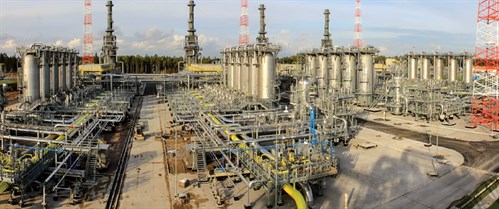
Alternatively, natural gas transmission for long distances without intermediate compression stations can be achieved by raising the pressure of the pipeline. The Nord Stream pipeline crosses the Baltic Sea from Vyborg, Russia to Greifswald, Germany through a 1,224-km route without any intermediate risers. Under the operating conditions of the pipeline, the gas temperature falls inside the hydrate and slug formation envelope of the “raw gas.”
The formation of slugs/hydrate might be detrimental for the integrity of the pipeline system; therefore, before natural gas is admitted into the pipeline, it must be processed so that neither chunks of liquid nor hydrates can form in the pipeline. Fig. 4 shows special gas processing units designed for gas submarine transmission without intermediate recompression.
 |
|
Fig. 4. Gas processing plant for international gas transmission. Photo courtesy of Siirtec Nigi SpA. |
Natural gas hubs. Hubs are essential tools for the development of a commodity market. They are places, physical or virtual, where natural gas can be freely traded and supplied through a market mechanism that requires diverse sources of gas supply (including domestic output, piping imports and overseas LNG shipment), storage facilities and a strong consumer base with competing buying interest.
Ideally, the best physical places to locate a hub are the points of convergence of diverse piping systems. By interconnecting these systems, natural gas can be moved from supply areas and exported to major consumption markets. In open markets, regulation plays a key role in allowing domestic and foreign participants to trade and freely access pipelines and storage facilities.
Henry Hub is one of the most well-known hubs. Located in Erath, Louisiana, Henry Hub interconnects nine interstate and four intrastate pipeline systems, and it has connectivity to gas storage facilities.
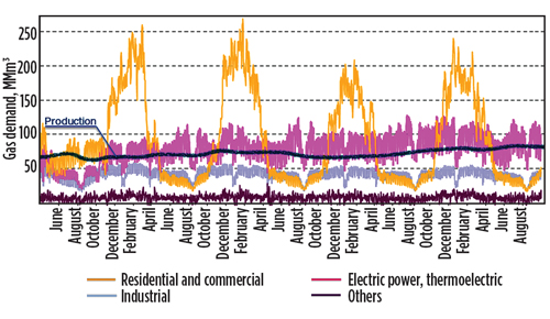
Seasonality management. Among fossil fuels, natural gas stands out for its marked seasonal variations of demand. The hourly, weekly, monthly and seasonal variation of consumption results from the combination of sectoral uses. The industrial, power generation, agriculture, transportation and residential sectors all make use of natural gas for their operations. Yet, each sector has a diverse consumption profile.
Fig. 5 shows the demand profiles for various sectors for Italy, a temperate-weather country in southern Europe. As can be seen, the industrial sector has an almost flat profile that tends to smooth the overall cycle, along with power generation. The daily oscillation of power generation, however, is increasing as a consequence of the growth in renewables. Supply of renewable energy experiences high and unpredictable variations, requiring gas turbines for power generation to be fed with natural gas to fill the supply/demand gap.
 |
|
Fig. 5. Gas demand pattern per sector in Italy. |
For the residential sector, monthly demand peaks are three times greater than the troughs. Fig. 5 shows that demand increases significantly from November through April and falls from the end of April through October. Overall, the trend in natural gas demand is a sequence of peaks and troughs, with considerable amplitude of swings.
Supply, on the contrary, has an almost flat course. This is for technical and economic reasons. In reservoirs, the gas must diffuse through the porosity of substrates; therefore, significant variations in gas extraction may disrupt production. It does not make economic sense to design a transmission pipeline for peak capacity lasting only a few months per year; therefore, only a limited allowance can be made for the supply profile, as depicted by the blue line in Fig. 5.
The imbalance between demand and supply can be handled by means of storage facilities in underground geological formations. These buffers can be categorized into three types:
- Underground gas storage (UGS) sites, including exhausted reservoirs, aquifers and salt cavities
- LNG storage tanks
- Line packs.
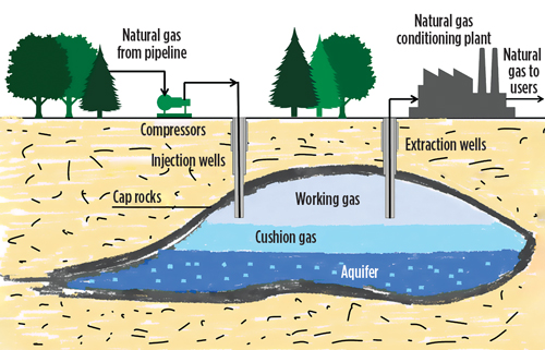
More than 80% of UGS is depleted reservoirs, which are relatively easy to convert into storage facilities. An aquifer is suitable for natural gas storage if the water-bearing sedimentary rock formation is overlaid with an impermeable cap rock. This requirement limits the use of aquifers as gas storage.
The ownership of the buffers belongs to transport companies, as regulations generally do not levy the spinoff of storage facilities from other assets in the natural gas supply chain. Typically, these facilities are located close to consumer areas.
Natural gas stored at approximately 150 barg in UGS comprises working gas and cushion gas, as shown in Fig. 6. The former is gas that can be extracted from storage to meet demand. Working gas amounts to about 50% of the total inventory (or 70%, in the case of salt caverns). The cushion gas provides the thrust needed in the supply phase. This gas cannot be extracted from storage without disrupting the facility.
 |
|
Fig. 6. Illustration of underground gas storage. |
During winter, when demand for natural gas surges, the volume needed to offset the extra consumption is provided by the working gas. From spring to autumn, gas coming from trunklines is compressed and injected into storage. In this way, the balance of demand and supply is ensured.
Salt caverns are carved from geological formations through a leaching process that can take as long as 4 yr. Among UGS sites, salt caverns are the most expensive facilities; however, their rapid cycling (inventory turnover) capability, coupled with responses to daily (and even hourly) variations in customer needs, reduces the yearly cost per 1,000 m3 of gas inventory injected and withdrawn. The inventory turnover capability makes salt caverns a suitable peakshaving tool, therefore justifying their high investment cost.
This description refers to the common use of UGS. However, UGS sites may also be used as strategic reserves for tackling unpredictable events, such as unseasonably cold winters or interruptions of flows due to unforeseen incidents, sabotage or geopolitical disputes. This UGS function is of utmost importance for those countries/states where import of natural gas represents a consistent fraction of gas consumption. Generally, this working gas cannot be extracted without government authorization.
UGS sites are also used for speculative purposes. If investors expect a future increase in price, they can buy the desired volume of natural gas on the market, store it in a UGS site and resell it when the price increases to or above the expected value. The difference between the sale price and the sum of the purchase price and storage cost should amount to breakeven or profit.
Eventually, UGS from depleted reservoirs provides suppliers with limited wiggle room to cope with temporary demand shocks. Nonetheless, the distribution system must be capable of meeting short-term peak demand and swing demand, which may occur on a daily or even hourly basis. In these cases, line packing and LNG storage are the other sources used to supplement supply.
The line pack technique makes use of the physical volume of gas contained in pipelines. At 80 barg–100 barg, a 40-in.-diameter, 1,000-km-long trunkline contains roughly 60 MMm3–100 MMm3. Variations in the pipeline operating pressure of a few bars provide modulation—limited to a few tens of MMm3—and flexibility of supply. This flexibility can be used to meet instant demand swings.
Unlike the distribution systems of other commodities, the role played by the natural gas midstream and downstream sectors goes far beyond connectivity of supply and demand. Gas pipeline systems allow the pervasive use of natural gas in fundamental sectors of modern economies and can react quickly to adverse events, thereby safeguarding the continuity of supply.
The capillary diffusion of trunklines and distribution networks, their interconnection through hubs, the timely coordination of entry points, the wide host of delivery points and the security offered by UGS make natural gas supply to end markets safe and reliable. GP
 |
Lorenzo Micucci is a Senior Director at Siirtec Nigi SpA. He has more than 30 yr of experience in the engineering and contracting industry, most of which have been spent in the natural gas sector. In 2001, he joined Siirtec Nigi in Milan, where he directed the process design and operations department and the research and development department. During his time as R&D head, three patents have been granted to Siirtec Nigi, two of which have been implemented on an industrial scale. At present, he is the Senior Director of the technology and marketing departments. Mr. Micucci also worked for Saipem (Snamprogetti) as a Plant Designer for integrated gasification combined cycle and GTL plants. He holds an MS degree in chemical engineering from the University of Bologna in Italy and is enrolled as a Qualified Engineer in the Register of Milan Order of Engineers.


Comments