
Fundamentals of turboexpander design and operation
A turboexpander is a rotating machine with an expansion turbine that converts the energy contained in a gas into mechanical work, much like a steam or gas turbine. A steam or gas turbine’s goal is to convert the mechanical work into useful power, by either driving an electric generator or being the prime mover for another rotating machine, such as a compressor or a high-power pump.
In applications that require the refrigeration of process gas, the distinction of a turboexpander is that it expands the gas stream for its own sake, and mechanical work is generated as a byproduct. This is not to say that the side effect of mechanical work is not useful. On the contrary, most turboexpanders likely drive a compressor or generator. In this case, the compressor or generator serves as a loading or braking device—a sink for the expander’s energy. Another common term for this type of machine is “compander,” although this is less common in the natural gas processing industry.
This article’s primary focus is cryogenic turboexpanders loaded by compressors, although many of the principles expounded are applicable to other types of expanders, such as an expander-generator.
Turboexpander applications. Turboexpanders were introduced in the mid-1930s when the first machine was designed and installed for air separation. The first turboexpander for a natural gas application was designed and installed in the early 1960s. Today, more than 5,000 units are in operation globally.
Cryogenic turboexpanders¹ find use in many applications. They are standard in the natural gas industry for liquefaction (FIG. 1) and dewpoint control. They are also used in the petrochemical industry for ethylene plants, air separation, refrigeration and power generation.
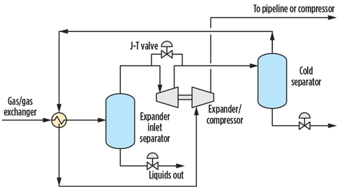 |
| FIG. 1. Typical natural gas liquefaction process. |
The two main markets for these machines are hydrocarbon processing and air separation plants. In both cases, there is a desire to change the state of a process gas to a specific pressure and temperature. Turboexpanders achieve these temperature targets by extracting relatively large amounts of energy and driving down temperatures accordingly. As such, they can be viewed as very efficient refrigeration machines.²
How does a turboexpander operate? A refrigeration cycle requires that the gas be greatly expanded to reduce its temperature. This is referred to as a Joule–Thomson (J-T) effect, and it can be accomplished with a valve. The J-T valve (or throttling valve) achieves a constant enthalpy expansion adiabatically, with no work output.
The expander is, in some sense, also a valve because it also accomplishes a sharp pressure drop; however, it accomplishes more than a valve because it also extracts work from the gas expansion via a turbine. By requiring the expanding gas to perform work, the resulting temperature is further reduced and the efficiency of the refrigeration cycle is improved.
The kinetic energy (work) produced by the turbine is absorbed by a “loading” element that is mechanically coupled to the turbine via a spindle or shaft. This can be a dyno (oil brake), an electric generator or a centrifugal compressor stage. For the latter two, turboexpanders afford the opportunity to utilize energy that would otherwise not be available with a J-T valve. An expander-compressor can be used as a pressure booster to meet a need in the process that otherwise would have necessitated a separate compressor driven by an electric motor or an engine.
FIG. 2 shows a cross-section of a typical turboexpander. The expansion stage (left side of the image) consists of a radial inflow turbine, often with variable-position inlet guide vanes. The typical turboexpander is designed as a 50% reaction turbine. This means that half of the static enthalpy change occurs through the stator, or inlet guide vanes, and the other half through the rotor, or expander wheel. The percent efficiency range that can be achieved by the turbine is between the mid-80s and low-90s. The compression stage (right side of FIG. 2) comprises a centrifugal compressor stage with a vaneless diffuser. The compression percent efficiency ranges between the mid-70s and low-80s at wide flow and head ranges.
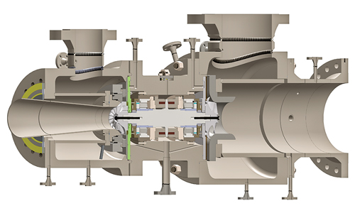 |
| FIG. 2. Typical turboexpander design equipped with active magnetic bearings. |
Over the years, many technological advances in design and manufacturing have allowed turboexpanders to contribute to improvements in the efficiency of multiple gas processes. Engineers have incorporated computer-aided tools, such as computational fluid dynamics (CFD), finite-element analyses (FEA) and computer numerical control (CNC) machining to enhance key features, such as compressor stage design, to maximize efficiency and reliability.
Preliminary sizing of a turboexpander. The original equipment manufacturer (OEM) must design the machine to operate at an optimal speed, given the process performance requirements. This speed is usually determined by the expander wheel’s best operating speed.
The compressor wheel is then designed to load the expander at this optimal speed. At times, the speed that is optimal for an expander can be too high for a reasonable compressor design. In this case, the OEM must resort to a reduction in speed to satisfy the overall goal of providing a machine that can operate reliably, with a good balance of expander and compressor performance.
The performance of the expansion turbine stage of a turboexpander can be stated in terms of a few basic parameters:
- Isentropic enthalpy drop, Btu/lb: ∆Hs
- Outlet volume flowrate, ft³/sec: Qout
- Speed, rpm: N
- Wheel diameter, in.: D
- Wheel tip speed, ft/sec (Eq. 1):
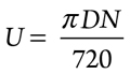
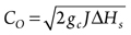
- Spouting velocity, ft/sec (Eq. 2a):
- Specific speed (Eq. 3b):
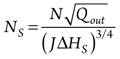
where
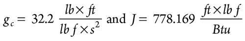 |
are for unit conversion.
Spouting velocity is defined as the velocity obtained if the isentropic enthalpy drop is converted to kinetic energy.a Note that different OEMs will generally have different equations for the specific speed parameter.b The important thing to understand is that manufacturers generally know the achievable efficiency and U/Co ratio of their expanders as a function of specific speed.
A typical process for performing an initial sizing is to first assume that the turboexpander will operate at a given specific speed. From this initial guess, an isentropic efficiency can be calculated based on an OEM’s efficiency vs. specific speed experience. Note, however, that the efficiency estimate will directly affect the expander outlet conditions, specifically the outlet volumetric flow rate, Qout. Therefore, this is an iterative process. After settling on a specific speed and efficiency, the required operating speed can be calculated from the specific speed relationship.
As a next step, the achievable U/Co can also be calculated from specific speed. Knowledge of Co directly gives the required tip speed, U. Combined with a desired operating speed, the tip speed gives the required diameter. The speed and diameter must be checked against the capabilities of the bearings and the compressor wheel required to load the expander. For instance, if the speed is too high for a given wheel diameter, then the bearings may not be able to support the rotor; or the stresses in the wheels may be too high, resulting in structural failure. If necessary, a lower speed may be selected and the process repeated until a satisfactory design is obtained. After the diameter and operating speed of the expander have been determined, the OEM can select an appropriate machine, or frame size.
Basic design and special features. Cryogenic turboexpanders are simpler in their construction than more intricate turbomachines, such as multistage centrifugal compressors or gas turbines. As with all turbomachines, they have several main components, detailed in the following subsections.
Rotor. A turboexpander rotor is typically composed of a shaft with an expander wheel mounted on one end and a compressor wheel mounted on the other. The wheels are usually milled from a solid piece of high-strength aluminum. The shaft is usually manufactured from a high-strength stainless steel bar or forging. The wheels are mounted to the shaft in a variety of ways. Torque is transmitted through methods such as cylindrical bores with keys, tapered fits with keys, dowel pins or polygon fits. Each wheel is secured to the shaft with a high-strength screw.
Bearings. Turboexpanders can be equipped with either oil bearings or magnetic bearings. In addition to supporting the weight of the rotor, bearings must overcome axial forces generated in the wheels due to the difference in pressures between the front and back of each wheel. The axial force of one wheel is intended to be as close as possible to the other, and the forces are pointed in opposite directions. This is not always possible due to fluctuations in gas operating conditions; therefore, excursions in thrust load (in either direction) are to be expected.
To accommodate this, the expander is fitted with two compound radial and thrust bearings. Oil bearings can be fixed-geometry or tilt-pad type, and require a clean, cool oil supply. It is common to see a compound bearing with a fixed geometry, tapered land journal and a tilt-pad thrust face. Users in the petrochemical industries seem to prefer active magnetic bearings (AMB). These bearings require a high-speed five-axis controller that maintains the rotor in a stable orbit. FIG. 3 shows three bearing style options.
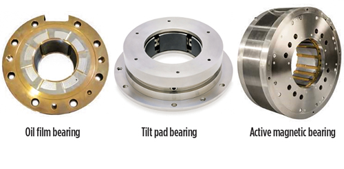 |
| FIG. 3. Turboexpander bearings options. Center and right images courtesy of Waukesha Bearings.. |
Turboexpander bearings are mounted inboard of the wheels. For this reason, the bearings are usually exposed to high-pressure process gas. If equipped with oil bearings, this means that the associated lubricating oil system must also be pressurized. This adds to the complexity of these machines from an overall system architecture point of view, whereas the turbomachine itself is quite simple in construction.
Seals. Given the hermetically sealed nature of the machine, as described in the description of bearings above, turboexpander shaft seals are typically single-port, non-contacting labyrinth seals. The labyrinth teeth can be located on either the static seal or the rotating shaft. Mechanical seals are not commonly used for these machines. They add unnecessary cost and complexity to the design, as well as extend the length of the overhung wheel weight from the bearings, making high-speed operation difficult to design in terms of rotordynamics.
Inlet guide vanes (IGVs). The inlet guide vanes are the variable stators of the expander stage. They serve to direct the incoming gas in a more ideal path toward the expander wheel, as well as function like a valve, by closing to pinch the flowrate. A variety of IGV designs can be found among different OEMs. Some choose a reduced number of vanes, four or five, and have simple adjustment mechanisms. Others incorporate a larger number of vanes, perhaps 11 or more, and have a more complex linkage mechanism, and even geared actuation mechanisms. All options have trade-offs, advantages and disadvantages. What is most important is that the vane count, expander wheel blade count and speed of the machine are aligned properly to avoid a potential structural resonance issue causing damage to the expander wheel.
Casings. Turboexpander casings are usually radial split and grouped in three distinct parts. The bearing housing is usually carbon steel and contains almost the entire machine, from expander wheel to compressor wheel, and everything in between, including the bearings and seals. The bearing housing is also known as the mechanical center section (MCS) or the rotating assembly. The expander casing is usually stainless steel, due to the low-temperature gas it must contain. For many OEM designs, it also houses the inlet guide vane assembly. The compressor casing is usually carbon steel. It forms the diffuser part of the compressor stage, as well as the collector or volute, depending on the type of design.
Spare parts. Due to their simplicity, turboexpanders do not require an extensive list of spares. As such, OEMs commonly offer a spare MCS or spare rotating assembly (SRA). This spare MCS contains, at a minimum, a fully assembled rotor, which includes the expander and compressor wheels and shaft, bearings, shaft and wheel seals, and sometimes even an inlet guide vane assembly. The idea is that in the event of a failure, instead of replacing specific parts, the entire MCS can be swapped and the damaged MCS sent to an OEM for repair.
Other spare parts can be supplied for auxiliary systems. Examples include spare seal gas and oil filter elements, control panel electronic components, or magnetic bearing controller-related spares.
Active magnetic bearings. An area of significant development in the turboexpander industry is the proliferation of active magnetic bearings (AMBs) as the support for the rotating element and for providing vibration and thrust control. Traditional applications for active magnetic bearings include offshore platforms (due to space constraints), petrochemical (because of zero tolerance for oil carryover/contamination of the process), remote locations, extreme climate (no need for lube oil temperature control) or whenever state-of-the-art data collection and management is desired. The petrochemical industry has long adopted AMB-equipped turboexpanders. The first generation of AMBs with analog controllers was placed in service in the early 1990s.
The lack of lube oil in a hermetically sealed machine is a paradigm shift in how conventional oil-bearing turboexpanders are operated and maintained. As the bearings are exposed to process gas, the process gas inherently must be exposed to the lubricating oil. A variety of operational problems and requirements can and do arise with this design configuration. Lube oil must be maintained at high quality and purity to ensure that viscosity levels are within required ranges for proper operation of hydrodynamic bearings. This requires replacement and flushing of the lube oil on a regular basis. Some end users shut down their turboexpanders twice a year for lube oil replacement alone.
Unexperienced operators can find themselves dealing with major oil carryover issues by failing to operate an oil-bearing turboexpander appropriately. For example, depressurizing a machine too quickly by way of a casing drain can lead to casings flooded with oil. Casings not drained properly can carry over oil to cryogenic processes, freezing lines and plugging exchangers. The startup process can take hours, especially in cold climates, due to the need to warm up the lube oil until it reaches the required minimum temperature. Finally, oil filters must be maintained routinely, along with many block valves, control valves and instrumentation.
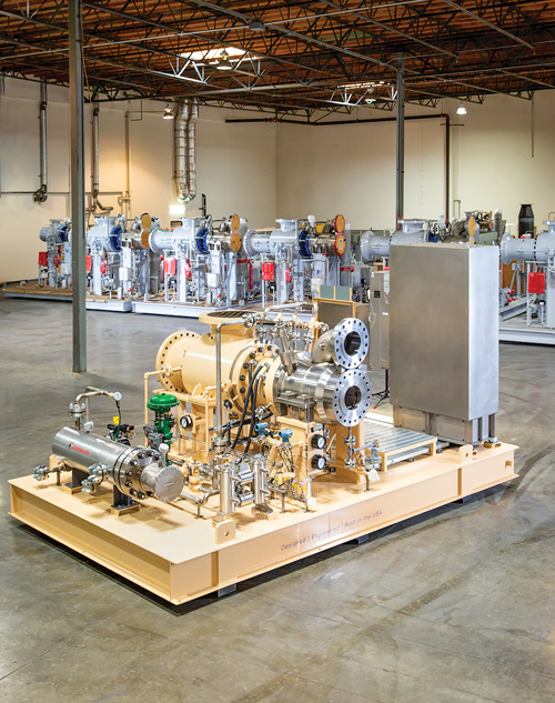
AMB suppliers are now progressing to a third generation of technology, namely next-generation digital control systems and controller designs. Interest is growing for AMB solutions among various industries, including installations within the most stringent military applications and within the U.S. NGL market. End users are beginning to embrace the many operational advantages that AMBs offer over their oil-bearing counterparts. FIG. 4 shows a typical AMB-equipped turboexpander skid.
 |
|
FIG. 4. Active magnetic bearing turboexpander-compressor with on-skid controller. Photo courtesy of L.A. Turbine. |
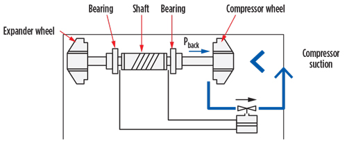
Control. As suggested previously, the turboexpander can be thought of as a rotating valve. It can be controlled like any other control valve (e.g., a J-T valve) by means of a 4-20 mA control signal to the inlet guide vane actuator, which adjusts the flow area in the inlet guide vanes. Most natural gas processing plants will use pressure control to maintain either expander outlet or compressor outlet pressure. Another possibility is to control the expander’s upstream pressure (also known as backpressure control). In the end, process dynamics should dictate the optimum control strategy.
Turboexpanders are usually not controlled by speed. A turboexpander can achieve power balance at multiple speeds for a variety of process conditions. As such, there is no single speed value that can be easily chosen to maintain a desired process condition. It is best if speed is allowed to vary with process variations in pressure, temperature, flow and composition. In this manner, speed becomes a dependent parameter in turboexpander operation. The speed of the machine is a result of the power balance due to the flowrates and pressure ratios across both the expander and compressor wheels. Speed should only be monitored and limited, not controlled, for ideal turboexpander operation.
Compressor surge control. Turboexpanders are typically supplied with very simple anti-surge control systems. Compressor surge can be a serious problem that can lead to a damaged turboexpander. It is a system phenomenon that occurs if the flow through the compressor is reduced below its surge limit. Operation in surge can cause a reversal of flow through the compressor leading to speed fluctuation, high vibration and thrust. The turboexpander is protected from surge by means of a bypass valve called the anti-surge valve (ASV). The ASV recycles compressor discharge gas to the compressor suction to lower head and increase flow.
Compressor suction and discharge pressure transmitters are used to calculate compressor differential pressure, and a differential pressure transmitter is used to monitor the compressor suction flow across the flow element. The anti-surge controller maintains a ratio between the compressor flow and the compressor differential pressure within a safe margin from the surge line.
Automatic thrust balancing system. Turboexpanders supplied in the oil and gas industry are commonly equipped with an automatic thrust balancing (ATB) system, also known as an automatic thrust equalization (ATE) system. This system controls a valve that connects the compressor inlet to the cavity behind the compressor wheel. By opening or closing, this valve can increase or decrease the pressure in this cavity, resulting in an increase or decrease in the thrust force in the direction of the compressor.
Oil-bearing machines actuate the ATB valve by means of a piston-cylinder device. Tubing lines from the cylinder on either side of the cylinder are connected to the thrust bearings. This cylinder actuates the ATB valve when there is a difference in oil pressure between the two thrust bearings (FIG. 5).
 |
|
FIG. 5. Schematic of a typical ATB system on an oil-bearing machine. |
Magnetic bearing-equipped machines use a valve actuator controlled by the main programmable logic controller (PLC). The PLC recognizes a thrust imbalance based on the difference in electric current in each thrust bearing and actuates the ATB valve to minimize the thrust difference.
Maintenance requirements. Turboexpanders typically do not have any regularly scheduled maintenance. If equipped with an oil bearing, the lube oil system will have filters that should be replaced at regular intervals, and general oil cleanliness should be maintained. This requires regular sampling and testing of the oil to ensure that it meets OEM required specifications. Magnetic bearing-equipped turboexpanders have even less maintenance requirements since they are primarily built of electronic components.
Most systems will include seal gas filters that should also be replaced at regular intervals. These filters, along with oil filters, are usually supplied with provisions for differential pressure measurement. The filters will need to be replaced if the differential pressure exceeds a level recommended by the OEM.
Common troubleshooting. The following is a list of common field problems and typical root causes and possible fixes:
- High thrust
- Open anti-surge valve: With an open anti-surge valve, there is inadequate pressure behind the compressor wheel to balance thrust, resulting in a high thrust load toward the expander side of the machine.
- Plugged expander wheel thrust holes: Expander inlet gas may be insufficiently dehydrated, leading to freezing gas constituents becoming trapped inside the expander wheel thrust holes and an increase in expander back wheel pressure and high thrust toward the expander side of the machine.
- Worn expander back wheel seal: With a worn back wheel seal, high-pressure process gas can leak behind the expander wheel at rates higher than can be relieved through the expander thrust holes. This can lead to an increase in expander back wheel pressure and high thrust toward the expander side of the machine.
- Worn compressor back wheel seal: With a worn back wheel seal, high-pressure process gas can leak behind the compressor wheel at rates higher than can be relieved through the ATB system. This can lead to an increase in compressor back wheel pressure and high thrust toward the compressor side of the machine.
- Excess seal gas flow to the compressor seal: When the flow to the compressor seal is too high, it may exceed the amount that can be relieved through the ATB system. This can lead to an increase in compressor back wheel pressure and high thrust toward the compressor side of the machine.
- Erratic anti-surge valve control
- Process conditions vary from design parameters: If the flowrate to the compressor is much lower than the design condition, and if the expander side also has not been reduced, this may lead to a surge condition.
- Compressor flow transmitter: Check that the compressor flow transmitter has been properly configured and its output matches the desired input by the anti-surge algorithm. For instance, the flow transmitter may be configured to output flow, whereas the typical anti-surge algorithm expects an output of orifice differential pressure.
- Anti-surge valve actuator: Check that the anti-surge valve actuator has been properly wired and configured.
- Compressor pressure transmitters: Check that the compressor suction and discharge pressure transmitters have been properly wired and configured.
- Anti-surge control parameters: Check the anti-surge control parameters in the controller and ensure that they are set according to the OEM’s specifications.
- High bearing temperature
- High current in AMB magnets: If equipped with magnetic bearings, high currents in the radial or thrust magnets can lead to high bearing temperature. Typically, the current levels will exceed allowable values before bearing temperatures reach alarm limits.
- Insufficient cooling gas supply: If equipped with magnetic bearings, insufficient cooling gas supply can be the problem. Check to make sure the cooling gas hand valves are sufficiently open.
- Insufficient cool oil flow: Ensure that the lube oil system is providing the required amount of flowrate at the supply temperature specified by the OEM. Oil flow is typically controlled by differential pressure.
- High shaft vibration
- Excess rotor imbalance: This can be caused by poor balancing or by wearing of rotating components over the life of the machine.
- Low oil viscosity: Oil supply may be too hot or may have lost viscosity due to dilution from natural gas entrainment.
- Aero induced vibration: Aero induced vibration caused by high process loads and/or excess liquids in expander wheel seals. This issue is more common with magnetic bearing-equipped turboexpanders.
- High shaft elongation (magnetic bearings)
- Insufficient cooling gas supply: Check to make sure the cooling gas supply is adequate and that valves, if supplied, are sufficiently open.
Industry specifications. Turboexpanders designed for the oil and gas industry are typically specified to conform to the API 617 specification, “Axial and centrifugal compressors and expander-compressors” (8th Ed.).3 The applicable chapters in this specification are Part 1, “General requirements,” which contains information pertinent to all types of turbomachines covered by the specification, and Part 4, “Expander-compressors,” which specifies requirements for expander-compressors. Among others, these requirements include performance, materials and methods of construction, auxiliary support systems (e.g., lube oil and seal gas supply), instrumentation and testing requirements.
API 617 also includes a new section, Annex E, in Part 1, which specifically addresses active magnetic bearings. In previous editions, AMBs were addressed as an Annex in Part 4, as a subsection of turboexpander requirements. In addition, this new section includes more detailed requirements for both OEMs and AMB suppliers, whereas the previous edition of API 617 included only informative content.
Other applicable specifications include API 614, “Lubrication, shaft-sealing and oil-control systems and auxiliaries,” which defines the requirements for oil lubrication systems and seal gas systems. API 670, “Machinery protection systems,” defines the requirements for machine health monitoring systems and their associated instruments, such as bearing temperature RTDs and shaft vibration probes and transducers.
Capacity rerates. As with other turbomachinery, a turboexpander has limits in its range of operation. Specifically, its flow capacity cannot be exceeded much beyond its design flowrate. The primary reason is the need to match gas and rotor velocities in various stages of the machine, resulting in certain required flow areas.
Coupled with the fact that gases are compressible and can choke (i.e., have a maximum flowrate), there is a maximum limit to how much gas can flow through the expander or compressor stages of a turboexpander. Therefore, a desire to increase flow through a turboexpander often requires a rerate involving extensive modifications of nozzle and wheel geometry. A few considerations should be kept in mind when evaluating a possible rerate.
Inlet guide vane open area. For a typical design, the inlet guide vanes are usually choked at the design point. Most OEMs will design the guide vanes to be able to open to a larger flow area than required at the design point to provide some margin for an increase in flow. This will allow a turboexpander to operate slightly above its maximum rated flow capacity. Additional flow will require a redesign of the inlet guide vanes to have a larger open area.
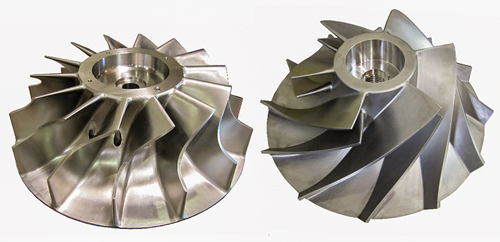
Expander wheel outlet area. The expander wheel’s capacity is limited by the throat area between the outlet of its blades (FIG. 6). This area can limit the flow capacity similar to the area of the guide vanes. A few options exist to increase the capacity of an expander wheel. The OEM can change the outlet angle of the blades; however, this can result in reduced efficiency for a given pressure ratio. Another option is to reduce the hub diameter at the wheel outlet. This increases the length of the blade in the radial direction and can cause a structural resonance by reducing the frequency of the blade’s first mode of vibration. A third option is to increase the size of the expander wheel itself. This is more drastic because it can require a modification to the inside of the expander casing.
 |
|
FIG. 6. Expander wheel (left) and compressor wheel (right). |
Compressor wheel inlet area. Like the expander wheel (FIG. 6), the compressor wheel’s capacity is limited by the throat area between its blades, although in this case at the inlet of the compressor. The options to increase capacity are also the same. Basically, this flow area must be increased by either modifying blade inlet angles, reducing the hub diameter or increasing the overall size of the compressor wheel. This last option can also lead to modifications of the compressor casing.
Bearings. The size of a machine’s bearings can limit several design parameters. A given bearing size and span between bearings can support a rotor of a certain overall weight, speed and overhung wheel weights. A redesigned set of wheels due to a rerate can exceed the load capacity or rotordynamic stability margins of the existing bearings, whether oil or magnetic bearings. The thrust limits can also be exceeded with a rerate, thereby requiring new, larger bearings and thrust collars.
Frame size increase. Ultimately, the casings themselves can limit the maximum flowrate because they can accommodate only a certain maximum wheel and inlet guide vane diameter. As a result, a substantial increase in flowrate can lead to a change of the entire machine to a larger frame size. This is because the original design may already be close to its frame size’s maximum capacity, so that even a slight increase in flow capacity can require an entirely new machine. On an oil-bearing machine, this can even lead to a completely new auxiliary oil system, since a larger frame size can require an increase in oil flow and cooling capacity.Bearings. The size of a machine’s bearings can limit several design parameters. A given bearing size and span between bearings can support a rotor of a certain overall weight, speed and overhung wheel weights. A redesigned set of wheels due to a rerate can exceed the load capacity or rotordynamic stability margins of the existing bearings, whether oil or magnetic bearings. The thrust limits can also be exceeded with a rerate, thereby requiring new, larger bearings and thrust collars.
To summarize, the basic mechanical configuration of turboexpanders, with the wheels placed outboard, requires relatively little effort to rerate, assuming the existing casings can be used. This is because new wheels can be designed and manufactured while the existing machine is still running. Once the parts are available, they can be installed in the field with relative ease, resulting in short downtime. When operators consider the return on investment for a rerate, they find the benefit to be obvious.
Repairs. In the unfortunate circumstance of a machine failure, it must be removed from the field and sent to a qualified repair facility. A major benefit of a simple design and construction is that the repair of a machine is usually possible with manageable costs and lead times.
In the worst case, a major failure can lead to damaged wheels, seals, shaft and bearings. These parts can be made new and can perform as well as the original machine, provided that critical clearances can be reclaimed. In less serious failures, repairs to important rotating parts can be expedited for a quick turnaround.
Takeaway. Turboexpanders are the ideal choice for processes with large pressure drops that require refrigeration or power recovery. Whereas a valve or an orifice can also be used to effectively drop pressure, turboexpanders extract useful work from a flowing gas stream. Isentropic efficiencies as high as 90% are readily achieved with a turboexpander, resulting in much lower discharge temperatures.
The simple construction and hermetically sealed design of turboexpanders generally lead to high reliabilities, with some plants operating the same turboexpander for many decades. The development of active magnetic bearings has made turboexpanders even more robust by eliminating the many drawbacks and requirements of conventional hydrodynamic oil bearings. Commonplace in the petrochemical industry, active magnetic bearings are becoming more popular in natural gas processing applications as their costs decrease and more competition is introduced among suppliers.
In the authors’ experience, the more plant designers and end users know about what is inside the “black box” of a turboexpander, the more successful they are as they make critical decisions about their equipment. The beginner who is involved in a turboexpander project will be better equipped to fulfill their role by being familiar with the contents of this article, and even those already familiar with turboexpanders will sharpen their knowledge. GP
LITERATURE CITED
- Jumonville, J., “Tutorial on cryogenic turboexpanders,” Proceedings of the 39th Turbomachinery Symposium, 2010.
- Bloch, H. P., Turboexpanders and Process Applications, 1st Ed., Gulf Professional Publishing, Houston, Texas, 2001.
- API 617, “Axial and centrifugal compressors and expander-compressors for petroleum, chemical and gas industry services,” 8th Ed., American Petroleum Institute, Washington, D.C., 2014.
 |
Tadeh Avetian is Director of Engineering at L.A. Turbine, responsible for identifying and defining research and development projects and directing turboexpander design for new and aftermarket equipment. Mr. Avetian is a California-registered professional engineer with BS and MS degrees in mechanical engineering from California State Polytechnic University at Pomona.
 |
Luis E. Rodríguez is a Design Engineer at L.A. Turbine, responsible for the mechanical design of turboexpanders. Prior to L.A. Turbine, he worked for 10 yr at Sulzer Turbo Services in La Porte, Texas. Mr. Rodríguez is a Texas-registered professional engineer with a BS degree from Universidad Simón Bolívar in Venezuela, and an MS degree from Texas A&M University.


Comments