
Remote, robotic removal of catalysts from reactors
In the 1970s, the first commercial remote-operated vehicles (ROVs) for the offshore oil and gas industry were developed. Prior to these, underwater inspections and maintenance operations were performed by personnel wearing heavy underwater suits equipped with breathing apparatus. A catalyst handling technician faces a similar scenario when entering vessels filled with nitrogen (N2) to vacuum the spent catalyst material. The number of fixed-bed catalytic vessels in the global refining and petrochemical industry is estimated to exceed 50,000 (average of 50–60 vessels per facility),1 and yet the process for catalyst removal has remained essentially unchanged for the past 75 yr.
In 2018, the industry’s first commercial robot for catalyst unloading was used to remove molecular sieve adsorbent from a dehydrator at an LNG plant in Australia. The development of a new, remotely operated robotic catalyst removal systema responds to increasingly stringent requirements to reduce human risk in inert, confined-space entry. It is the culmination of a 3-yr development effort from conception and design to prototyping and testing, and it represents a potential game-changer in the industry.
This article showcases the challenges associated with existing catalyst removal techniques, as well as the inherent safety advantages that the new system has shown in its pilot operations. One case study demonstrates the system’s elimination of the need for confined-space entry under inert conditions during adsorbent unloading from a dehydrator. The second case study examines the use of the system on a wet catalyst bed under water flood conditions. The final case study illustrates the use of the system in removing material built up at an angle of repose, at temperatures unsuitable for human entry.
 |
|
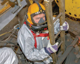
FIG. 1. Worker entering a vessel.2 |
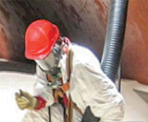
Traditional catalyst unloading. Based on existing technology, a rough estimate of the number of worker days of risk exposure due to confined-space entry during catalyst unloading (Fig. 1) exceeds 10,000 d/yr globally (assuming catalyst removal every 5 yr with an average confined-space entry duration of 1 d per vessel).1 Catalyst removal is commonly achieved by a worker standing on the catalyst and manipulating the end of a high-volume vacuum hose (Fig. 2).
 |
|
FIG. 2. Worker vacuuming catalyst.3 |
The challenges faced by a catalyst handling technician are similar to that of a deep-sea diver. The working conditions require supplied breathing air to sustain life, and one mistake can lead to catastrophic consequences. While the offshore industry has seen the development of the ROV to greatly reduce the requirement for underwater diving at oil platforms, the safety improvements in the catalyst handling industry have focused primarily on improved personal protective equipment (PPE) and procedures.
Many vessels require inert conditions throughout the catalyst unloading process, typically because pyrophoric scale on the catalyst can auto-ignite in the presence of oxygen (O2). Anti-panic helmets have been developed that consist of a clamshell design bolted to the occupant’s head. The helmet cannot be removed by its occupant—a design that has become standard best practice—after fatalities occurred due to technicians removing their helmets in the vessel. It is likely they had become claustrophobic and were not thinking clearly, potentially influenced by heat exhaustion. In operation, breathing air is supplied to keep the helmet at a slight overpressure.
Fatalities have occurred in the catalyst handling industry due to asphyxiation, exposure to heat and fire, falling from heights, pressure buildup and engulfment under catalyst.4 A study conducted by the US Chemical Safety Board identified 85 N2-exposure incidents in the US between 1992 and 2002, resulting in 80 deaths and 50 injuries.5 While improvements have been implemented, fatalities continue to occur.
In 2014, a catalyst handling worker was killed at a refinery in Germany. The worker was vacuuming catalyst from the bottom of the vessel when he reported hard sections of catalyst via the intercommunication system. Ten minutes later, the worker called for help and the safety crew initiated rescue activities. The worker reported that a wall of catalyst had collapsed on him and that he could feel heat coming from within the catalyst. Outbreathing from the helmet provided enough O2 to cause pyrophoric scale on the catalyst to ignite. Communication with the entrant gradually slowed, and then stopped. The burned body was recovered only after 350 ft3 of catalyst had been removed.
While fatalities present the ultimate risk, the health impact on catalyst handling technicians when performing manual vacuum operations is also significant. The ergonomic position taken by the worker is to crouch over in hot protective clothing while maneuvering a heavy vacuum hose around the vessel. They cannot drink water while inside the vessel because of the air supply system. To get out of the vessel for a break, they may need to climb 40 ft of ladder to reach the manway, which could be as narrow as 18 in.
Development of remote, robotic catalyst removal system. Early attempts to create a catalyst removal robot were made by Greg Kraus and Ray Arnold of Catalyst Services Inc. in Texas. With a patent published in October 2008, the design involved a vacuum line connected to an articulating nozzle, supported against the sides of the vessel using stabilizing arms.5 One of the key challenges the inventors likely faced was achieving a catalyst removal efficiency comparable to that of a person. Catalyst changeouts are often critical-path activities during a plant turnaround, meaning delays are costly for the operator. This challenge is likely what prevented the robotic arm concept from being commercialized.
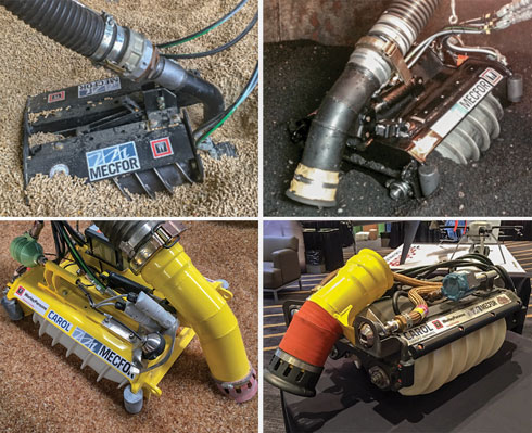
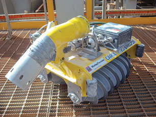
The development team for the new system took a different approach. The aim was to develop a machine that sits on the catalyst and vacuums it while moving around. The “quicksand-like” characteristic of the catalyst was the critical parameter to overcome. The amphirol (screw-propelled vehicle) was selected (Fig. 3).
 |
|
FIG. 3. Robotic catalyst removal systema prototype development—clockwise from top left: Versions 1.0, 2.0, 2.1 and 3.0. |
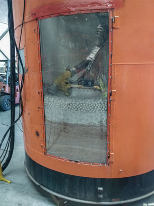
The development of the amphirol catalyst unloading robot was adapted from a technology that the manufacturer had previously implemented for the red mud lakes of alumina refineries. The technology, which uses worm gear propulsion, allows the device to move on a semi-liquid substance. The combination of a lightweight aluminum frame and large-diameter screws provides a buoyancy effect on the catalyst (Fig. 4). The system has been tested on the full range of media density (40 lb/ft3–80 lb/ft3) and particle size (0 in.–1 in.) encountered in catalyst unloading.
 |
|
FIG. 4. Robotic catalyst removal system testing. |
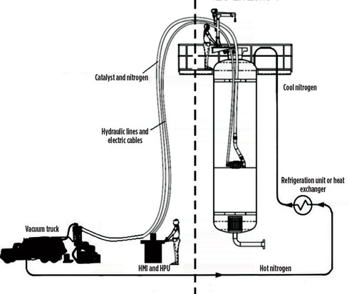
The amphirol is controlled remotely from the top platform or at grade (Fig. 5). Movement around the catalyst bed is achieved via remote-operated direct-drive hydraulic motors. Meanwhile, the vacuum head, which is connected to the robot via a hydraulic cylinder, can be raised and lowered remotely to achieve an optimum catalyst-to-air/N2 efficiency. The system’s in-vessel electrical equipment is rated for use in Zone 1 and Class 1 Division 2 hazardous areas (ATEX, IEC Ex and AEx certification on the entire system). The equipment is operational up to a temperature of 167°F (75°C). For manual unloading, the vessel will be cooled to less than 100°F (38°C) for human entry, and atmospheric pressure is maintained. The system provides productivity advantages since it can be deployed while the vessel is still hot. It can also operate continuously throughout the shift, meaning the support crew can have a staggered lunch break and eliminate 12%–20% of downtime.
 |
|
FIG. 5. Robotic catalyst removal system operational setup. |
Risk mitigation is a critical aspect of any project. The robotic catalyst removal system team has approached the device’s development using the same rigor as would be applied on a major greenfield project. Examples of outputs from the risk assessment process include hydraulic oil low level trip to minimize potential leakage from a broken hose; continuous monitoring of vessel lower explosive limit, oxygen content and temperature to minimize the risk of fire and/or explosion; and operating procedure with step-by-step guidance and sign-off to ensure effective operation of the equipment.
Case studies. The case studies presented highlight the use of the new catalyst removal system under a range of challenging circumstances typically encountered during catalyst unloading.
Dehydrator unloaded under inert conditions. The system was used to remotely remove adsorbent from a dehydration vessel, avoiding the need for worker confined-space entry under inert conditions.
 |
|
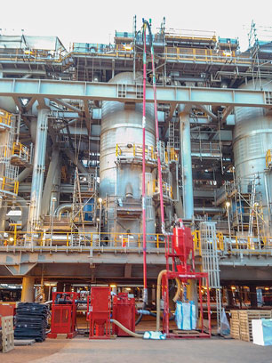
FIG. 6. Dehydrator vessel. |
The dehydration vessels, which remove water from gas before it is liquified, consist of 2,000 ft3 of molecular sieve adsorbent, which is low-density catalyst. When unloaded under an N2 blanket, the catalyst is dry and free-flowing. When unloaded manually, the technician’s boot will sink into the material up to the knee. The plant is located in a tropical climate with temperatures in the vessel reaching up to 120°F (49°C). The catalyst sits between a lower and upper steel mesh screen with ceramic balls at the top. The vessels are of a large diameter, with no gravity dump capability. The client was seeking to eliminate confined-space entry under inert conditions.
 |
|
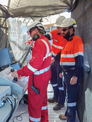
FIG. 7. Control station. |
The new system was used to unload the dehydration vessels under inert conditions, with no requirement for human entry into the N2 environment. This was the first time that the system had been used in an operating plant. The robot was first deployed to remove 1-in. ceramic balls from above the top mesh screen. The screen was speared and removed from the top manway. The system was then used to remove the molecular sieve adsorbent, navigating to all parts of the vessel, including in and around the moisture probes located toward the bottom of the bed. The vessel was then opened to air so that the bottom internals could be removed.
The system remotely removed more than 95% of the molecular sieve adsorbent from the vessel, including the ceramic support material at the top of the bed. Inert conditions were maintained throughout the process, and the requirement for confined-space worker entry in the O2-deficient atmosphere was eliminated.
 |
|
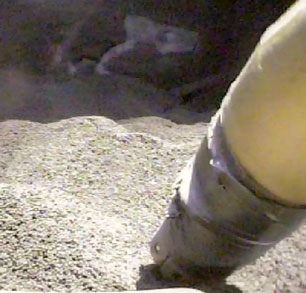
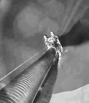
FIG. 8. Camera on robot. |
Dehydrator unloaded under water flood conditions. The system was successfully used to remove wet material from another dehydration vessel following a water flood operation. This removal took place in a portion of the same plant as in the previous case study.
Some operators have sought to move entirely away from confined-space entry under inert conditions. This can be achieved by flooding the vessel with water several times to flush away the residual hydrocarbons. In the case of pyrophoric material, the catalyst is kept relatively wet by slowly lowering the water level in the bed as the catalyst is removed. Although the catalyst can then be vacuumed in an open-air environment, the water introduces additional hazards for the occupants, and full suits with breathing apparatus are still required.
 |
|
FIG. 9. Robotic catalyst removal system post-job. |
The system was used to vacuum the wet adsorbent. The screws were effective in allowing the robot to maneuver on the catalyst bed, thereby maintaining an even level of catalyst during removal, which was important because the catalyst was not free-flowing.
The use of the system on the wet adsorbent showed how the technology can be used in tandem with the water flooding method. The time at risk for confined-space entry was significantly reduced.
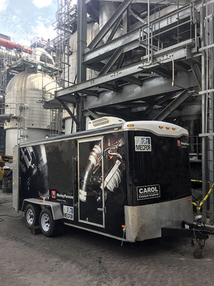
Gas shift reactor unloaded post-gravity dump. The system was used to remotely remove built-up catalyst at an angle of repose, with vessel temperatures exceeding 120°F (49°C). This was the first time that the system was used in a live operating plant in the US.
 |
|
FIG. 10. Control system trailer. |
Catalyst from the gas shift reactor vessel was removed in the first instance using a dump nozzle located at the bottom of the catalyst bed. This allowed for catalyst to be gravity-dumped from the vessel; however, not all catalyst was removed. The residual catalyst can be up to 40% of the total vessel volume. Workers are typically required to enter the vessel to vacuum the remaining material and must be wary of the built-up catalyst around the vessel walls and the associated risk of being buried. The pyrophoric material also tends to heat up if the N2 purge is insufficient to maintain inert conditions. At this plant, the supply of N2 was low and vessel temperatures were difficult to control.
The system was used to unload the residual catalyst material (post-dumping) in the gas shift reactor vessel. It was operated in temperatures not suitable for human entry. The system successfully removed the catalyst until a hot spot on the catalyst bed caused the plastic prototype screws to melt. Hot catalyst beds are not uncommon, and workers will on occasion feel heat through their boots, at which point they must get
to the ladder before the soles of their shoes melt.
This use of the system demonstrated that the robotic catalyst removal technology can be used effectively, in combination with gravity dumping, to minimize the time spent by workers inside confined spaces during catalyst unloading. The vessel temperatures following the catalyst dumping operation were still too high for human entry; however, the use of the catalyst removal system allowed the job to continue.
 |
|
FIG. 11. Camera on top of vessel. |
Although a set of screws was destroyed due to a hot spot in the catalyst bed, this incident highlighted the reason that robotic catalyst removal is being introduced as an alternative to manual vacuum unloading. A new set of 3D-printed aluminum screws are in production and are expected to withstand catalyst temperatures of greater than 200°F (93°C).
Future work. In some cases catalyst can be fused, normally as a result of a process upset prior to the shutdown or extended runs between changeout. During in-house tests, the system has broken through a layer of crust created using a mixture of carbon and mortar. The screws on the unit are effective in catalyst conditions with mild agglomeration or “shelving” (buildup of sticky material against the walls after dumping). However, additional implements are being developed to extend the capabilities to heavily agglomerated or coked beds, typically encountered in heavy oil applications.
The catalyst removal system’s robot is now remotely operated using a joystick and video camera footage from inside the vessel. A joint industry project with a university in Brisbane is underway to implement automation of the robot movement around the bed. The goal is for the system amphirol to automatically move around the bed to maintain an even catalyst service and to automatically adjust the vacuum head position to optimize catalyst removal efficiency.
Takeaway. As the industry’s first commercial, fixed-bed catalyst unloading robot, the robotic catalyst removal systema aims to reduce the associated risk of placing people inside vessels. This could help kickstart a robotics revolution for the onshore oil and gas industry, like that seen with ROVs in the offshore industry.
The system has a straightforward design with few moving parts. By using screws for propulsion, it moves freely on the surface of loose material. It is lightweight and easy to maneuver inside the vessel using a joystick and live video feedback. Additionally, the system facilitates effective vacuum removal of catalyst with no requirement for human entry during the bulk catalyst unloading phase of vessel changeout.
The system development team has challenged the status quo that catalyst unloading must rely entirely on personnel. The robotic catalyst removal system has the potential to radically alter what has been done the same way for almost 75 yr. GP
Literature cited
- “2017 worldwide refining survey,” December 5, 2016, online: https://www.ogj.com/downloadables/survey-downloads/worldwide-refining/2017/2017-worldwide-refining-survey.html
- Mourik, “Catalyst handling services,” online: http://www.mourik.co.uk/catalyst-handling-services.php
- Catalyst Handling, “Setting new standards,” online: http://www.catalysthandling.com
- Malewitz, et al., “A deadly industry,” 2015, online: http://www.ehstoday.com/safety/deadly-industry
- US Chemical Safety and Hazard Investigation Board, “Hazards of nitrogen asphyxiation,” Safety Bulletin No. 2003-10-B, June 2003.
Note
aCAROL (Catalyst Removal Amphirol)
 |
Chris Jansen is Program Manager at WorleyParsons in Brisbane, Queensland, Australia, and co-inventor of Advisian Digital’s robotic catalyst removal technology, CAROL™ (Catalyst Removal Amphirol). He developed his plant knowledge and process safety experience as a chemical engineer at BP’s Bulwer Island refinery in Brisbane, Australia. He then joined WorleyParsons in 2014, where he soon set out to transform his idea of robotic catalyst unloading from concept into reality. He is now managing the global rollout and commercialization of the technology. Mr. Jansen graduated with first-class honors from the University of Sydney with degrees in chemical engineering and commerce.
 |
Andrew W. Sloley is Principal Consultant at Advisian (WorleyParsons Group) in Houston, Texas. He is responsible for consulting on refinery and petrochemical optimization and refinery-petrochemical integration. He manages consulting projects that that range from unit optimization to entire complex integration, technology selection, best-practices implementation and reliability improvement. Mr. Sloley developed his plant and technology knowledge through 40 yr of experience with operating, vendor, engineering and consulting firms. He publishes extensively and participates in many API, AFPM and AIChE activities. Mr. Sloley holds a chemical engineering degree (hons) from the University of Tulsa and is a licensed Professional Engineer in the state of Texas.
 |
Scott Schroeder is Senior Technical Consultant at Advisian (WorleyParsons Group) in Houston, Texas. At Advisian, he is responsible for gas processing and petrochemical technology. His responsibilities include economic evaluation, technology selection and operational excellence support. He has worked for more than 20 yr in cryogenic gas processing, LNG, gas purification, refinery offgas processing, NGL fractionation and several novel processes. Mr. Schroeder received his BS and MS degrees in chemical engineering from the University of Nebraska. He is a registered Professional Engineer in the state of Texas and the province of Alberta. He is also the co-inventor on two patents, with a third patent pending.


Comments