
Process design overview for upgrading a gas-to-methanol facility
J. Harker and A. Sanchez, INGEPROX Process Plant Services, Viña del Mar, Chile; and A. Gupta and A. English, IHI E&C International Corp., Houston, Texas
With the surge in natural gas production in the US, gas-to-methanol plants are receiving renewed interest. Not only are new methanol plants being built, but existing plants are also being revamped to increase and optimize their production.
Methanol is used as a feedstock to produce chemicals such as acetic acid and formaldehyde, which, in turn, are used in products like adhesives, foams, plywood and solvents.1 Methanol is also used in the production of methyl tertiary butyl ether (MTBE), a gasoline component that improves air quality, as well as in the production of dimethyl ether (DME), a clean-burning fuel with similar properties to propane. Furthermore, methanol is a key component in biodiesel, a renewable fuel that can be used in place of, or blended with, conventional diesel fuel.
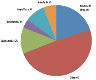
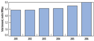
US demand for methanol has been continuously increasing. In 2014 alone, the US imported approximately 4.5 metric MMtpy of methanol, which is equal to 68% of the total US demand for methanol for that year (Figs. 1, 2).2
 |
|
Fig. 1. Global production of methanol by region, 2014. |
 |
|
Fig. 2. Methanol demand in the US. |
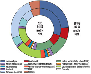
In recent years, the use of methanol in the production of olefins—referred to as methanol-to-olefins (MTO)—has grown rapidly. Worldwide, MTO production is expected to expand at a remarkable pace, becoming the largest end‐use market for methanol by 2019 (Fig. 3).3
 |
|
Fig. 3. Methanol use worldwide by derivative, 2013 and |
Scope of gas-to-methanol plant upgrade. An overview is presented here of the major process design considerations evaluated and implemented for the upgrade of an existing natural-gas-to-methanol plant. The plant is located in Beaumont, Texas and was built in 1967 by DuPont with an original capacity of 550 metric Mtpy of methanol from natural gas. At the time, it was the largest gas-to-methanol facility in the world.
Over the years, the plant has undergone several upgrades, including the addition of an ammonia synthesis loop in 2000 that added 265 metric Mtpy of ammonia (NH3) production. The plant was idled in 2004 due to unfavorable market conditions, and was acquired by OCI and its partners in 2011. The new ownership has restarted the plant and undertaken a comprehensive upgrade project. The upgrade, referred to as the “debottlenecking project,” was completed in 1Q of 2015. Production using the upgraded design commenced in May 2015.
The facility uses proprietary steam methane reforming technology4 to generate synthesis gas (syngas) from natural gas feedstock. The syngas is subsequently converted to methanol in a methanol reaction loop. The purge gas from the methanol synthesis loop is routed to the adjacent NH3 synthesis plant.
The debottlenecking project included the following upgrades:
- Increase of reformer tube diameter to extend reformer life and provide additional capacity
- Addition of a prereformer to increase capacity
- Addition of a saturator to recycle wastewater and reduce liquid effluents from the unit
- Addition of a selective catalytic reduction (SCR) unit to reduce nitrogen oxide (NOx) emissions from the reformer flue gases
- Revamp of the reformer flue gas coils to improve thermal efficiency
- Revamp/addition of the reformed gas heat exchangers to increase capacity and provide saturator water heating
- Addition of new equipment to the NH3 plant
- Revamp of the reformer furnace with ultra-low NOx burners, providing higher heat duties
- Revamp of reformer combustion air preheaters for the new burners
- Upgrade/revamp of methanol syngas compressors, including changeout of low-pressure and high-pressure casing rotors and installation of a larger turbine drive to meet the higher power requirement
- Upgrade/replacement of the tray design installed in the splitter and refiner columns for better efficiency and capacity
- Addition of fin-fan coolers to condense excess steam from the process and recover as condensate to reduce water import
- Addition of a new flare dedicated to reformed gas to decrease gas venting to atmosphere during outages and/or startup conditions.
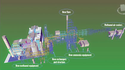
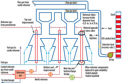
Fig. 4 provides a pictorial overview of some of the major upgrades to the facility.
 |
|
Fig. 4. New additions/upgrades under debottlenecking project scope. |
Goals of upgrade project. The objectives of the debottlenecking project were not only to increase the production capacity of the plant, but also to optimize the energy consumption of the facility and reduce environmental emissions. The project goals were to increase the production capacity of both the methanol and NH3 plants by 25% (Table 1).
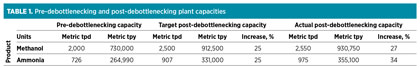
In actual operation, the plant has exceeded the target capacity increase. The net energy efficiency of the plant has improved significantly through the modification of existing equipment and the addition of new equipment using state-of-the-art technologies. NOx emissions have been reduced by more than 90%; sulfur dioxide (SO2) and carbon dioxide (CO2) emissions have also decreased significantly.
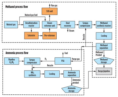
Facility process overview (pre-debottlenecking operation). The block flow diagram in Fig. 5 indicates the process steps utilized in the facility, which are outlined in the following sections.
 |
|
Fig. 5. Block flow diagram for the facility. |
Methanol manufacturing process. This process begins with natural gas. Traces of sulfur must be removed to avoid poisoning of the reforming and synthesis catalysts used in the process. The natural gas is passed through a catalyst bed, where it is desulfurized.
The desulfurized gas is then mixed with steam, and this mixture is passed through the catalyst-filled reformer tubes. The reaction of natural gas (principally CH4) with steam forms primarily hydrogen (H2), carbon monoxide (CO) and CO2—i.e., syngas. The endothermic reaction requires heat, which is provided by burning fuel gas in the reformer furnace. The fuel gas is composed of natural gas, purge gas from the methanol reactor circulation loop and several other small purge gas streams from the NH3 plant. The major steam methane reforming reaction is shown in Eq. 1:
![]() (1)
(1)
The hot flue gases generated from the combustion of the fuel are used to preheat the reformer feed, generating and superheating steam, followed by preheating of the combustion air. Subsequently, the spent flue gas is emitted to the atmosphere through the reformer stack.
The process (or synthesis) gas leaving the reformers is then cooled, compressed in the synthesis gas compressor to 1,550 psig and sent to the synthesis section as makeup gas.
Methanol synthesis. The synthesis of methanol occurs in a two-stage methanol reactor system, in the presence of a copper catalyst. The synthesis gas is a mixture of recycle gas from the methanol reactor circulation loop and fresh makeup gas from the reformers. The gas is circulated through the reactors by a recirculating compressor. On each pass, a portion of the CO, H2 and CO2 is converted into a methanol/water mixture referred to as crude methanol. Major reactions are shown in Eqs. 2 and 3:
![]() (2)
(2)
![]() (3)
(3)
The mixture leaving the reactors (i.e., methanol, water and unreacted gases) is cooled to separate the condensable liquid from the non-condensable gases using water-cooled heat exchangers; the separated unreacted gases are mixed with fresh makeup gas and recycled back to the reactors. Condensed crude methanol is stored in the crude storage tank prior to refining.
A packed-tower wet scrubber (i.e., crude tank scrubber) is used to recover methanol vapors from the crude storage tank offgas. Crude methanol is purified in a four-column distillation process to remove water and other impurities. Purified methanol is then stored in two 7.5-MMgal methanol storage tanks prior to shipment.
To control the buildup of excess H2 and undesirable gases (e.g., methane, CH4; and nitrogen, N2) in the synthesis loop, a portion of the unreacted high-pressure gas is continuously purged from the system. When the NH3 plant is not operating, the purge gas is routed to the reformer fuel gas system and burned as supplementary fuel gas.
Methanol and ammonia plant interaction. When the NH3 plant is operating, high-pressure purge gas from the methanol synthesis loop is routed from the reaction area to the NH3 process. The gas is first water-washed in a scrubber column to remove trace amounts of methanol. The recovered methanol/water stream is then routed to the crude methanol storage area for the recovery of the contained methanol. The purge gas is then sent to a pressure-swing absorption (PSA) unit to separate the H2 from the CH4, CO, CO2 and residual methanol. The pure H2 stream is then suitable for use in NH3 synthesis.
The remaining purge stream of H2, CO, CO2 and CH4 (PSA tail gas) is sent to the reformers as supplementary fuel. The heating value of the H2 removed from the purge stream is replaced with an equivalent heating value of natural gas to maintain constant heat input in the reformers.
Ammonia plant. The NH3 plant produces liquid NH3 from H2 and N2. H2 from the PSA unit or imported via pipeline from local suppliers combines with an N2 stream supplied by local suppliers via pipeline. This mixture, which is controlled to provide a 3:1 H2-to-N2 molar ratio, is referred to as NH3 syngas.
The NH3 syngas passes to the makeup gas compressor, where it is compressed and mixed with recycle gas from the NH3 synthesis loop. The mixture of fresh syngas and recycle gas is preheated and constantly circulated through the NH3 converter. On each pass through the NH3 converter, a portion of the H2 and N2 react over beds of an iron oxide catalyst to form NH3, per the reaction shown in Eq. 4:
![]() (4)
(4)
This equilibrium reaction, which is sensitive to changes in temperature and pressure, allows approximately only 20% conversion of H2 and N2 to NH3 per pass through the converter. The optimum temperature in the NH3 converter is maintained by internal heat exchangers between the conversion beds.
The converter effluent, a gas mixture of NH3 and unreacted H2 and N2, passes through heat recovery exchangers, condensers, NH3 refrigeration chillers, and separators to condense and remove the liquid NH3 from the syngas. The liquid NH3 is depressurized into a letdown vessel and sent to the refrigeration system for further cooling.
The refrigeration section of the NH3 process is a closed loop system provided with an electric-driven refrigeration compressor. The system includes a series of condensers, accumulators, chillers and separators. Liquid NH3 from the refrigeration system can be pumped via pipeline to either of OCI’s two storage tanks. Each of these tanks has a capacity of 20 Mt and is provided with compressors for refrigeration purposes.
Design considerations for the facility upgrade. The debottlenecking project required detailed evaluation of all existing equipment in the facility and determination of the pathways to increase the capacity. The orange-highlighted blocks in the flow diagram in Fig. 5 represent major new equipment added to the facility. New equipment, including a prereformer, a fired heater, an ultra-purification vessel, a saturator system and a number of heat exchangers were added upstream and downstream of the existing reformers.
The reformer tubes were replaced with tubes with larger inner diameters using state-of-the-art metallurgy. The burners in the reformers were replaced with ultra-low-NOx burners. An SCR system was installed to reduce NOx emissions. A new flare system was installed to burn gases during startup or outage conditions, and also to burn gases that were previously vented to atmosphere.
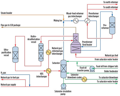
Addition of ultra-purification vessel, fired heater and prereformer. An ultra-purification vessel, fired heater and prereformer were added. A prereformer was added to the plant to increase the reforming capacity of the plant. The extra heat duty required for the prereformer was provided by a separate fired heater, which has two sections. The lower section is used to heat the natural gas feed to the prereformer, while the upper section is used for heat optimization. A schematic for this arrangement is shown in Fig. 6.
 |
|
Fig. 6. Natural gas treatment, saturator and prereforming flow chart. |
The prereformer has stringent requirements for the amount of H2S in the feed as the prereformer nickel-based catalyst is easily poisoned by sulfur. An ultra-purification vessel containing a copper- and zinc-based catalyst was added to ensure a maximum of 10 ppb H2S in the prereformer feed gas. An additional exchanger was added for heat optimization.
The prereformer is a fixed-bed reactor filled with highly active nickel-based steam reforming catalyst. Steam is added to the process gas feed prior to the prereformer, up to a steam-to-carbon molar ratio of 2.8. Adding steam upstream of the prereformer increases the reforming duty, which has a slight impact on the catalyst volume. In the prereformer, higher hydrocarbons are completely converted into a mixture of CH4, carbon oxides and H2.
Use of the prereformer has several advantages:
- The prereformer yields significant energy savings by lowering the overall steam-to-carbon ratio in the primary reformer feed.
- Cracking of higher hydrocarbons in the top of the primary reformer tubes can lead to carbon depositions, which can increase the resistance to gas flow in the reformer tubes and may impair catalyst activity. This impairment lowers the rate of the reforming reaction and can cause local overheating or “hot bands” in reformer tubes that result in premature tube wall failure. These potential problems have been eliminated, as all higher hydrocarbons are converted in the prereformer upstream of the reformer.
- The prereformer also leads to an increase in reformer catalyst life, since most of the remaining sulfur in the hydrocarbon feed is absorbed by the prereforming catalyst.
Addition of saturator column. A saturator column (Fig. 6) was added to the plant, allowing for the recycling of process wastewater and reducing liquid discharges from the facility. The natural gas to the reformers is passed through the saturator column, where it absorbs water by countercurrent contact with the process wastewater stream. This lowers the amount of makeup steam required to be mixed with the natural gas to be fed to the reformers.
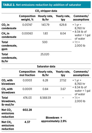
The saturator column also reduces the environmental emissions of CO2 and CH4. These emissions were previously routed to a CO2 stripper, which was in service in the pre-revamp design. The CO2 stripper had an atmospheric vent leading to significant emissions, which was eliminated in the new design through the use of the saturator. The saturator blowdown provides lower liquid emissions. Table 2 compares the emissions for pre-debottlenecking and post-debottlenecking cases.
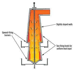
Reformer tubes upgrade. The facility uses proprietary steam methane reforming technology to generate syngas from natural gas. This technology uses a side-fired heater design with burners located along lateral walls and the flames vertically arranged. The radiant section comprises a firebox with a row of catalyst tubes, with two terraces on either side of the tubes where the burners are installed. The catalyst tubes are flanged at the top to allow loading and unloading of the catalyst. A schematic of the arrangement is shown in Figs. 7 and 8.
 |
|
Fig. 7. Reformer tubes revamp and SCR unit flow chart. |
 |
|
Fig. 8. Schematic of a reformer system. |
To increase the production capacity of the plant, throughput in the reformer tubes was increased by upgrading the tubes. The tubes were replaced with tubes of an increased inner diameter while keeping the outer diameter the same, resulting in tubes with a lower wall thickness. This was made possible through the use of improved metallurgy for the reformer tubes with a proprietary alloy of cast austenitic steel of 35% nickel, 25% chromium plus niobium, titanium and others. The inner diameter of the tubes was increased from 4.25 in. to 4.75 in., while the outer diameter was kept at 6.09 in.
The top and bottom flange-to-tube connections were designed to accommodate the new tube wall thickness with a suitable flange for the required service. The original RTJ connections were replaced by a special high-temperature Kammprofile gasket type.
Other options were considered and rejected. Increasing the number of tubes was technically ruled out, as this would lead to reduced tube spacing and inadequate firing in the reformers. For similar considerations, increasing the outer diameter of the tubes was also not a viable option.
Replacement of burners. Increasing the flowrate of the feed also required an increase in the firing of the burners. The plant has two reformers—north and south. In the pre-revamp design, the south reformers used ultra-low NOx burners, and the north reformers used low-NOx burners from the same vendor.
The vendor5 recommendations were implemented for the upgrade of the burners. These recommendations included:
- Standardizing the burner capacity
- Replacement of all tiles
- Replacement of all burner tips
- Replacement of all inlet air dampers
- Introduction of fuel-staged burner technology.
Replacement of all tiles, and the redesign of the burners for both the upper and lower terraces for the same duty of 3.95 MMBtu/hr each, resulted in a higher fired capacity for both units. All burner tips were replaced; with this design, all burner tips, both unit-to-unit and terrace-to-terrace, are interchangeable primary-to-primary and stage-to-stage. The redesign required all tiles to be changed, which allowed the upper tiles and lower tiles for both units to be made interchangeable. The replacement air entry dampers were also designed to be interchangeable.
The energy consumption in the burners was reduced by adding a preheating system to the air supply to the burners. The preheating system consisted of steam coils, which use excess steam from the plant to heat the combustion air. The coils reduced the heat duty of the burners, leading to lower natural gas consumption and an increase in plant efficiency.
Modification of existing burners was an economical option, but this was ruled out due to several disadvantages, including insufficient capacity increase, impact on the firing ratio between burners on the first and second levels, and impact on the interchangeability of the burners and tiles.
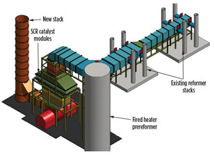
Addition of SCR. The environmental air emissions for NOx was reduced to meet the Texas Commission for Environmental Quality (TCEQ) regulations by including a selective catalytic reduction (SCR)6 unit to treat the flue gas. The introduction of an SCR unit is a proven, cost-effective means of achieving a high level of reformer and fired heater NOx emissions reduction.
SCR is a means of converting NOx (with the aid of a catalyst and NH3) into N2 and water (H2O). A vanadium/titanium-based catalyst is used in the SCR reaction. The NH3 is added to a stream of flue or exhaust gas and reacts with the NOx to form N2 and H2O.
Basic reactions for an NH3-based SCR system are shown in Eqs. 5 and 6:
![]() (5)
(5)
![]() (6)
(6)
where NOx = NO, NO2 .
With the installation of a new SCR unit, the reformer furnaces and the prereformer fired heater achieve 0.008 lb of NOx/MMBtu, which is the best available control technology (BACT) during normal operations.
NH3 plant upgrade. In addition to the methanol plant, a debottlenecking exercise was conducted on the NH3 plant to increase the capacity. This project involved revisiting the design margins available on all equipment in the plant. The equipment that had insufficient margin to reach the new required design were replaced or supplemented by additional equipment.
The NH3 synthesis converter was determined to have sufficient margin for the additional flow requirement. New exchangers were added to improve performance, including an additional NH3 chiller. Some of the separator vessels were replaced, and additional cooling was achieved with fin-fan air coolers.
 |
|
Fig. 9. Layout of SCR unit. SCR minimizes NOx emissions by |
The syngas and refrigeration compressors were evaluated, and changes were required to meet the new nameplate target. Compressors were upgraded with rotor and driver modifications. The compressor stationary parts were determined to be sufficient, although rotating parts were modified.
Additional considerations. The new syngas production capacity, based on the revamped reformers and the new prereformer, was used to evaluate the performance of other equipment in the methanol plant:
- Reformer flue gas heat recovery coils
- Reformer burners
- Reformed gas heat recovery exchangers
- Syngas compressor and driver
- Circulator and driver, methanol converters
- Converter effluent heat recovery exchangers
- Distillation
- Cooling water system
- Water treatment system
- Steam system.
In general, the equipment had sufficient margins to accommodate the increased capacity. The steam system required additional considerations, and the steam balance for the plant was revisited. An additional steam condenser was added to the plant to recover and recycle boiler feedwater from the excess steam generated.
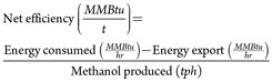
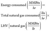
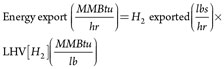
Impact on net efficiency. Net and gross efficiencies of the plant can be used as parameters to determine the impact of the upgrades and additions to the plant on energy usage in the facility. These efficiencies are defined as shown in Eqs. 7–10:
![]() (7)
(7)
and
 (8)
(8)
where
 (9)
(9)
and
 (10)
(10)
Table 3 compares the efficiencies for the pre-debottlenecking operation, target post-debottlenecking operation and actual post-debottlenecking operation. The lower heating value of natural gas and H2 is used to compute the total energy consumption and energy export from the facility. In the post-debottlenecking operation, H2 from purge gas is used in the NH3 plant, and the heating value of the H2 is deducted from the energy consumed to compute the facility’s net energy consumption for the production of methanol.
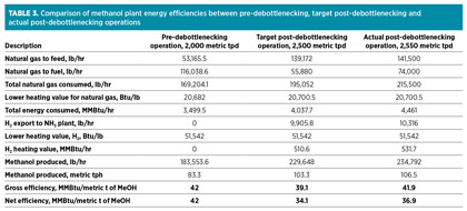
From Table 3, the target improvement in the net efficiency of the plant was approximately 23%. In actual operation, the plant has achieved approximately 12% improvement in net efficiency. This reduced efficiency improvement is attributed to ingress air leakage in the reformers, which leads to additional fuel consumption and other inefficiencies attributed to the age of the plant.
Summary. The debottlenecking project has been completed to increase the capacity of the OCI gas-to-methanol plant located in Beaumont, Texas. The total project cost is estimated at $368 MM. The upgraded plant has been successfully operating since May 2015 and has proven to operate at production rates above the debottlenecking design capacity.
The debottlenecking project involved numerous considerations: increasing the capacity of the primary reformer, replacement of burners and associated equipment, and the additions of a prereformer, an ultra-purification vessel, fired heaters, heat exchangers and associated equipment and controls.
Newer technologies are enabling more efficient plants to be designed. Many of these technologies feature design aspects that have become standard for the design of new methanol plants. With increased natural gas production in the US, it is likely that more gas-to-methanol plants will be built that are more efficient, more economic to operate and more environmentally friendly than their predecessors built years ago. GP
LITERATURE CITED
- Methanol Institute, “Applications for Methanol,” http://www.methanol.org/Methanol-Basics/Methanol-Applications.aspx
- Jim Jordan and Associates.
- MMSA, IHS.
- Foster Wheeler, “Terrace Wall Steam Reformers,” http://www.fwc.com/What-We-Do/Fired-Heaters/Steam-Reformers/Terrace-Wall-Steam-Reformers.aspx
- John Zink Hamworthy Combustion, “Process burners parts & service,” http://www.johnzink.com/products/process-burners
- CECO Environmental, “Peerless SCR system,” “http://www.peerlessmfg.com/solutions/environmental/selective-catalyst-reduction.html
 |
Jamie Harker is an operations specialist working in process operations, commissioning, startup and detailed engineering for oil, gas and chemical plants. He has 18 years of experience in plant operations and project engineering. He studied power engineering at the Southern Alberta Institute of Technology in Canada.
 |
Alejandro Sanchez is the director of INGEPROX Chile SpA. He was a formerly a process engineer at Methanex Corp. and has more than 28 years of experience in engineering, operations, supervision and management in the methanol and ammonia industry. Mr. Sanchez holds an MS degree in chemical engineering from the Universidad of Concepción in Chile.
 |
Ashish Gupta is a process engineer at IHI E&C International Corp. and has more than 13 years of process engineering and research experience. Several of his projects have involved the development of emerging gasification and syngas technologies and engineering for pioneering plants. Dr. Gupta holds a PhD in chemical engineering from the University of Florida.
 |
Alan English is vice president of engineering development at IHI E&C International Corp. He has more than 40 years of management, project and process engineering experience in the oil, gas and petrochemical industries. Mr. English has been involved in the development of new technology for synthesis gas production and purification plants, and he has experience in design, construction and startup of methanol, MTBE, cogeneration and gas processing facilities.


Comments