
Impacts of benzene and piperazine concentrations on LNG plant capacity
K. K. Hwang and S. Kim, SK E&C, Houston, Texas
Benzene emissions can have an effect on LNG plant capacity when a vent gas incinerator is not present. Here, a typical amine sweetening unit for acid gas removal, featuring a typical lean feed gas composition, is modeled using commercial amine sweetening software to calculate annual benzene emissions rates. The maximum allowable benzene content in a given feed gas rate is set by US Environmental Protection Agency (EPA) benzene emissions limits.
Two parameters—benzene concentration in the feed gas stream and piperazine content in the methyldiethanolamine (MDEA) solution—are used to determine LNG plant capacity. LNG plant capacity is described by an empirical curve fit equation. This equation provides a method to predict LNG plant capacity when a vent gas incinerator is not present.
Understanding the effects of benzene emissions rates on LNG plant capacity provides operators and designers a basis for the interpretation and manipulation of a broad range of feed gas compositions in LNG plant design.
Parameter overview. Benzene, toluene, ethylbenzene and xylene (BTEX) are present in natural gas streams and are picked up in the exit CO2 stream of the amine unit. Typically, the vent gas is incinerated through a thermal oxidizer to meet EPA BTEX emissions limits. BTEX components are listed by the EPA in the Clean Air Act of 1990 as some of the 188 hazardous air pollutants. The EPA sets a standard of 25 tpy for total aromatic compounds emitted by any given plant. A 10-tpy limit also exists on each individual aromatic compound that can be emitted.
The reasons1 for the restrictions are as follows:
- Benzene is a human carcinogen that promotes leukemia
- Toluene exposure can lead to reproductive or developmental effects
- Ethylbenzene affects the blood, kidneys and liver
- Xylene exposure can affect the central nervous system, leading to respiratory and cardiovascular problems.
Therefore, most gas operations incinerate BTEX, which are then absorbed in the amine unit and eventually released to the atmosphere to resolve the disposal issue of BTEX components in the vent gas stream.
However, the vent gas incinerator (thermal oxidizer) is a major source of flue gas, such as NOx and CO. The NOx and CO emissions rates from the thermal oxidizer could pose a major issue in obtaining local environmental air permits. In addition, the vent gas incineration is a thermal oxidation process in which the BTEX components are combusted at a temperature of 1,500°F. Since most of the vent gas stream is water-saturated CO2, a considerable amount of fuel gas is required for this operation. In other words, the vent gas incineration process can be operating cost-prohibitive from a fuel-usage standpoint.2
The other challenge posed by the thermal oxidizer comes from a construction viewpoint. According to National Fire Protection Association Standard 59A, process equipment containing LNG, refrigerants, flammable liquids or flammable gases shall be located at least 50 ft from the ignition source. The separation distance could provide another problem, since most small-scale LNG feed gas treatment systems inclusive of amine units are designed by modular fabrication.
The modular fabrication provides benefits such as an accelerated schedule, lower installed cost and increased reliability for LNG plant operations. Therefore, efforts to replace the vent gas incinerator with adsorption technology have drawn attention, and are under study. In this work, the authors provide the example of the removal of vent gas incineration from amine regeneration in the feed gas treatment portion of an LNG plant, and explain how this modification would affect LNG plant capacity. More specifically, the authors review the configuration of the feed gas treatment system and explain how benzene emissions rates from the amine regenerator can impact the capacity of an LNG plant without a vent
gas incinerator.
In this study, the authors use a commercial process simulator to model a typical acid gas removal unit (AGRU) without a vent gas incinerator. The model allows for the predicted measurement of annual benzene emissions rates for the two parameters, which are benzene contents in the feed gas stream and piperazine concentrations in the amine solution.
Requirements of feed gas treatment. In an LNG plant, natural gas from the gathering system must be treated before liquefaction can take place. Four major categories of contaminants in the raw feed gas are considered potentially damaging to the liquefaction process: mercury, heavy hydrocarbons, acid gas and water.
Mercury is known to cause stress cracking in brazed aluminum heat exchangers that are used in the cryogenic section. To prevent this stress cracking from occurring, the typical mercury specification for LNG is set at 10 Ng/m3. Mercury can be easily removed by conventional methods, such as a non-regenerable metal oxide guard bed. In addition, a sulfur-impregnated mercury-sulfur guard bed is used to meet the EPA H2S emissions limit.
The optimal location of the lead-lag beds is upstream of the AGRU, since the vent gas stream with H2S from the amine regenerator is not supposed to be incinerated. Also, the heavy hydrocarbon (HHC) removal unit should be placed upstream of the amine unit so that a significant amount of BTEX is not released into the acid gas along with the CO2 from the amine regenerator.
CO2 removal from natural gas using amine to very low levels (< 50 ppmv) is required to prevent freezing in the cold box. In a typical commercial amine process, an aqueous alkanolamine solution is in counter-current contact with natural gas containing CO2 in an absorber column. Finally, water must be removed from the gas stream prior to liquefaction to avoid freezing in the cold box. These treating facilities are an essential part of LNG plants, helping ensure reliable LNG production. As discussed in the previous section, this case study highlights the AGRU to address benzene emissions without a vent gas incinerator.
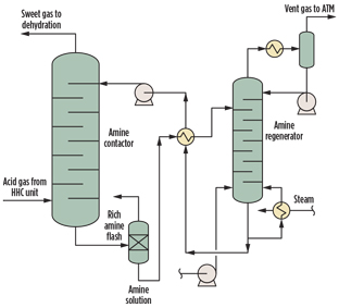
Modeling of AGRU. In this study, a typical amine sweetening unit (Fig. 1) is modeled using a commercial process simulator. An aqueous MDEA solution is in counter-current contact with natural gas containing CO2 in an absorber column. The MDEA reacts with the acidic CO2 gas to form a dissolved salt, allowing purified natural gas to exit absorber. The rich amine solution is regenerated in a stripper column to produce an acid gas stream concentrated with CO2, and is eventually vented to atmosphere without incineration. The lean solution is then cooled and returned to the absorber, allowing the process to repeat in a closed loop.
 |
|
Fig. 1. AGRU process scheme. |
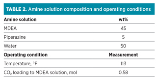
The acid gas stream, MDEA solution and operating parameters used for the study are summarized in Tables 1 and 2.
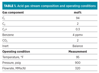
Typically, feed to LNG plants is composed primarily of methane, together with ethane, propane, butane and heavier components. A typical lean gas feed composition is used for the higher content of CO2 gas in the study. All stream properties of the amine unit are calculated using amine sweetening software in a commercial process simulator. Benzene content and composition of amine solution are varied for the sensitivity studies, irrespective of the performance credit of the HHC removal unit.
Results and discussion. Benzene is the least soluble aromatic component in LNG and poses the highest risk of freezing in the cold box. Therefore, benzene content is used as a target specification for the operation of the HHC removal unit in the LNG plant. The benzene content in the AGRU feed can vary, depending on the performance of the HHC removal unit in conjunction with CAPEX and OPEX.
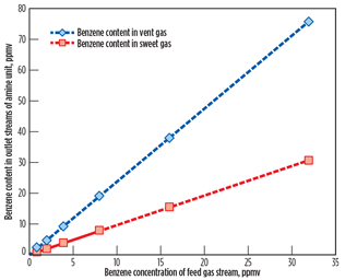
Benzene contents in the vent gas stream from the amine regenerator and sweet gas stream from the amine contactor are shown in Fig. 2 as a function of the benzene concentration of the AGRU feed gas stream.
 |
|
Fig. 2. Benzene content in outlet streams of the AGRU. |
Bullen et al.3 reported that the solubility of benzene in 50 wt% MDEA solution at 110°F should be approximately 0.017 scf/gal. However, as shown in Fig. 2, a very small amount of benzene is absorbed in the MDEA solution due to low partial pressure of benzene in the feed gas stream. By increasing the benzene concentration of the feed gas stream, benzene contents in sweet gas and vent gas streams display an increase. From the benzene contents in the vent gas stream of the amine regenerator, represented by a diamond symbol in Fig. 2, annual benzene emissions to the atmosphere are calculated based on a feed gas flow of 320 MMscfd.
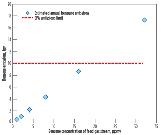
Fig. 3 reports the calculated annual benzene emissions rate in tpy, in terms of benzene concentration of the feed gas stream, for the case study of 320 MMscfd of feed gas flow. The calculated annual benzene emissions rate and the EPA emissions limit are designated by the blue diamond symbol and the red dotted line, respectively. The EPA limit of 10 tpy is taken to indicate that approximately 18 ppmv (maximum) of benzene content is allowed in the feed gas stream.
 |
|
Fig. 3. Calculated yearly benzene emissions at 320 MMscfd. |
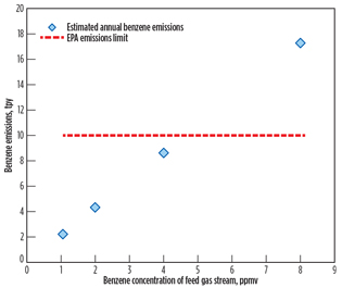
Since LNG plants are typically designed with multiple trains for larger production rates or operational flexibility to meet client needs and commercial requirements, the feed gas flow of the case study is extended to 4 × 320 MMscfd. As expected, the benzene loading at the feed gas flow of 4 × 320 MMscfd shifted to a lower concentration in comparison to the feed gas flow of 320 MMscfd to meet the EPA emissions limit, as shown in Fig. 4. In other words, the HHC removal unit upstream of the AGRU must reduce the benzene content to approximately 4.5 ppmv (maximum) to meet the EPA benzene emissions limit.
 |
|
Fig. 4. Calculated yearly benzene emissions at 4 × 320 MMscfd. |
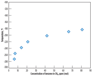
As stated earlier of the study result, there is a high risk of precipitation of benzene in the LNG product, due to its higher freezing point compared to cyclohexane and other aromatic components. Therefore, the maximum benzene content of 4.5 ppmv, meeting EPA limits, must be examined so that freezing does not occur in the LNG product. Experimental solubility data for benzene in methane from Neumann4 are shown in Fig. 5. According to the solubility data, approximately 8 ppmv of benzene is theoretically soluble in liquid methane at the typical liquefaction temperature of –250°F. Consequently, the maximum benzene content of 4.5 ppmv meets the LNG specification and the EPA benzene emissions limit, as well.
 |
|
Fig. 5. Solubility of benzene in methane (reproduced from |
The benzene content is determined by the performance of the HHC removal unit, which is located upstream of the AGR unit. For instance, the performance of temperature swing adsorption removing HHC inclusive of benzene is dependent on adsorbent volume (CAPEX) and regeneration cycle (OPEX). Specifically, the benzene content of the AGRU feed gas stream could be reduced at the cost of CAPEX and OPEX.
Eventually, the reduced benzene content can increase LNG plant capacity, meeting the EPA benzene emissions limit. To investigate the dependency of LNG plant capacity on benzene concentration, the same calculation methods described in Fig. 3 are conducted, varying the feed gas flowrate. In this calculation, the benzene emissions rate of 9 tpy is taken as a threshold point determining the benzene content in the feed gas stream, considering a 10% safety margin on the EPA emissions limit.
 |
|
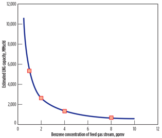
Fig. 6. Estimated LNG plant capacities. |
Fig. 6 reports estimated LNG plant capacity as a function of the benzene concentration of the feed gas stream. The LNG plant capacity decreases as benzene content in the feed gas stream increases to meet the EPA emissions limit. The dependency of the LNG plant capacity (Ca) on the benzene concentration (Bz) of the feed gas stream is well described (R2 = 0.99) by the empirical curve fit (solid line) shown in Eq. 1:
![]() (1)
(1)
where the fit constant has a unit of ppmv × MMscfd.
The other parameter affecting the benzene emissions rate of the vent gas is the amine solution. Amine’s reactivity with CO2 and benzene’s solubility in amine solution could factor into the benzene emissions from an AGRU without a vent gas incinerator.
MDEA is preferably used as an absorbent in applications involving CO2 removal from natural gas in LNG production due to its low regeneration energy. However, its reaction with CO2 is extremely slow, and the absorption process is controlled entirely by resistance to mass transfer in the solvent phase. For this reason, 5% of piperazine in MDEA solution was used in the modeling study of the AGRU. Piperazine is a cyclic diamine that reacts with CO2 approximately 10 times faster than MDEA.
To further investigate piperazine’s effect on the benzene emissions rate of the vent gas stream, a commercial amine sweetening simulation was conducted, varying piperazine concentration in the MDEA solution and maintaining the same benzene concentration of 4 ppmv in the feed gas stream.
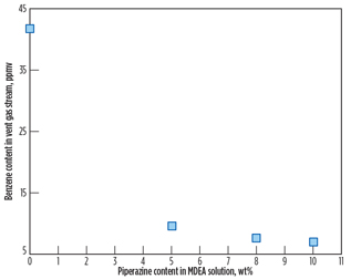
Fig. 7 shows the benzene content in the vent gas stream as a function of piperazine concentration. According to the simulation result, benzene content in the vent gas stream decreases as piperazine concentration increases. From the benzene contents in the vent gas stream shown in Fig. 7, yearly benzene emissions to atmosphere are calculated based on a feed gas flow of 4 × 320 MMscfd and benzene content of 4 ppmv in the feed gas stream.
 |
|
Fig. 7. Benzene content in the vent gas stream at 4 ppmv |
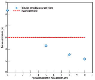
Fig. 8 shows that the yearly benzene emissions rate decreases as piperazine loading increases. As discussed previously, piperazine is a promoter absorbing CO2 rather than benzene. As a result, benzene content in the vent gas stream decreases as piperazine’s strength in amine solution (50 wt%) increases. In other words, it is likely that benzene’s solubility decreases as the MDEA fraction in the amine solution decreases. The study result is enhanced by reference study results3,5 showing that the solubility of benzene in the MDEA solution is reduced by as much as 30% as MDEA concentration decreases by 10%. More detailed analysis on benzene’s solubility in piperazine should be conducted in a separate study.
 |
|
Fig. 8. Estimated yearly benzene emissions at 4 ppmv of |
To investigate the dependency of LNG plant capacity on benzene and piperazine concentrations, the same calculation method and the same EPA emissions criteria described in
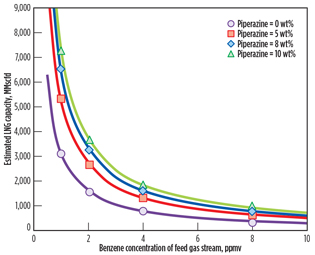
Fig. 6 are conducted, varying the feed gas flowrate. As shown in Fig. 9, LNG plant capacity increases as piperazine concentration in the MDEA solution increases at the same level of benzene concentration of the feed gas stream.
 |
|
Fig. 9. Estimated LNG plant capacities at various benzene |
The dependency of LNG plant capacity (Ca) on benzene concentration (Bz) of the feed gas stream is well described (R2 = 0.99) by the empirical curve fit (Ca = A/Bz) and summarized in Table 3 for all piperazine loading rates.
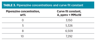
The curve fit constant linearly correlated with the piperazine concentration. The slopes and intercept of the linear regression were 418.9 MMscfd . ppmv . wt%–1, and 3,150 MMscfd . ppmv–1, respectively (R2 = 0.99). By compiling the fit constant into the empirical curve fit (Ca = A/Bz), the LNG plant capacity can be expressed in terms of benzene and piperazine concentrations using the curve fit shown in Eq. 2:
![]() (2)
(2)
To the authors’ knowledge, neither benzene nor piperazine concentration dependency on LNG plant capacity has been previously reported. Ultimately, with knowledge of the benzene concentration (0 < Bz ≤ 8 ppmv) and piperazine concentration (0 ≤ Pi ≤ 10 wt%), Eq. 2 provides a powerful method for making predictions of LNG plant capacity where a vent gas incinerator is not present. In other words, the contribution of benzene emissions without a vent gas incinerator can also be extended to typical gas processing and treating plants.
Ultimately, understanding the effects of benzene emissions rates on LNG plant capacity provides a basis for operators and designers to interpret and manipulate a broad range of feed gas compositions in LNG plant design. GP
LITERATURE CITED
1Majumdar, D., A. K. Mukherjeea and S. Sen, “BTEX in ambient air of a metropolitan city,” Journal of Environmental Protection, Vol. 2: 2011.
2Morrow, D. and K. Lunsford, “Removal and disposal of BTEX components from amine plant acid gas streams,” Proceedings from the 76th annual GPA convention, 1997.
3Bullin, J. and W. Brown, “Hydrocarbons and BTEX pickup and control from amine systems,” Proceedings from the 83rd annual GPA convention, 2004.
4Neumann, A., R. Mann and W. Von Szalghary, “Solubility of solid benzene in liquid hydrocarbons,” Kaeltetech Klim, Vol. 24, 1972.
5Critchfield, J., H. Holub and F. Mather, “Solubility of hydrocarbons in aqueous solutions of gas treating amines,” Proceedings from the Laurance Reid Gas Conditioning Conference, 2001.
 |
Kenneth K. Hwang is a registered professional chemical engineer with more than 17 years of experience in the oil and gas industry, and in research. He received his PhD in chemical engineering from Texas A&M University. Dr. Hwang works for SK E&C as a senior process engineer. He has expertise in natural gas processing, LNG, LPG and ethylene plant design.
 |
SuckHee Kim is a principal process engineer with more than 22 years of engineering, procurement and construction (EPC) and front-end engineering design (FEED) experience in the oil and gas industry. Mr. Kim’s specific areas of technical expertise include LNG liquefaction technology, NGL processing and natural gas treatment. He works for SK E&C as a principal process engineer.


Comments