
Consider key factors in pipeline wall thickness calculation and selection
S. Zardynezhad, Toyo Engineering Canada Ltd., Calgary, Canada
Pipeline wall thickness plays a significant role in mitigating the risk of loss of mechanical integrity and pipeline failure—scenarios that pose danger to people and to the environment. Many factors must be considered in calculating and selecting the economic thickness for pipelines, as the limited factors considered in a code thickness formula are not sufficient.
Here, the wall thickness calculation of pipelines is based on international codes and standards, and lessons learned in pipeline thickness calculation and selection are discussed.
Pipeline failure can be deadly. On September 9, 2010, at 18:11 PDT, a 30-in. natural gas transmission pipeline exploded in a residential neighborhood in San Bruno, California. Thirty-eight homes were destroyed and eight people were killed as a result of the blast. The US Geological Survey registered the explosion and resulting shock as a 1.1-magnitude earthquake.
Pipeline failure studies show that the risk of main failure causes, or modes, can be mitigated by selecting a suitable pipeline wall thickness. Table 1 lists main pipeline failure modes and the influence of wall thickness on relevant risk reduction, culminating from the author’s experience.
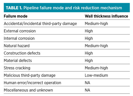
Statistics show that the most common failure mode is third-party interference—i.e., externally applied mechanical forces. Other key failure causes are corrosion, material defects and natural hazards. Wall thickness is the largest risk-reduction mechanism for most pipeline failures because, by increasing the wall thickness, the frequency of failure will decrease significantly.
Thickness calculations play an important role in mitigating not only the risk of pipeline failure, but also the cost of a pipeline project. The calculations also impact the project timeline because of their effect on manufacturing and construction timelines.
Pipeline thickness calculation factors. Pipeline thickness code formulas take into account a limited number of factors and loads in thickness and stress analyses. It is the responsibility of the engineer to determine supplemental factors based on specific loads. Also, the engineer must address the necessary protection and risk-reduction mechanisms for each possible failure mode. Several essential factors should be considered in pipeline wall thickness calculations, as outlined here.
Applicable codes, standards and specifications. The first steps in conducting pipeline design and wall thickness calculations are to determine the proper codes, standards and specifications. Each code and standard may use different design formulas and factors to calculate wall thickness.
Geotechnical report. Geotechnical data and soil information factor prominently in pipeline design and thickness calculations. A pipeline order should not be placed unless geotechnical and soil reports have been carefully studied and understood.
Pipeline survey. A survey is a key document for pipeline design. It includes necessary information that may impact strength and stress calculations, such as the existence of traffic crossings, muskegs, slope and soil movement areas, railways, hydraulic shock areas and flood regions.
Local regulation.1 Local regulation must be considered in addition to the applicable codes, standards and construction specifications for thickness calculations and allowable stress levels. For example, in Canada, Clause 6.9.25 of the Energy Resources Conservation Board (ERCB) Directive 56 includes allowable stress levels for steel, aluminum and polyethylene pipeline materials. Stress level is defined as the allowable stress in the wall of a pipe that is produced by the pressure of the fluids in the pipeline.1 After thickness is calculated based on Canadian Standards Association (CSA) Z662,2 then the stress level is verified as per the ERCB.
Stress study. Flexibility analysis is the main goal of the pipeline stress study. A buried pipeline will expand toward the ends or bends as temperature increases; however, the central portion of the pipeline will be fully restrained by the force of soil friction. This expansion creates a soil friction force that is proportional to the length of the expanding part. A pipeline stress study using computerized software or a simple spreadsheet should be conducted.
Minimum design metal temperature (MDMT). The MDMT may change the material and impact test requirements. The MDMT should be based on the lowest operating temperature or the lowest reported ambient temperature, whichever is more severe. The engineer should consider the lowest installation temperature and soil temperature when selecting a suitable MDMT. If using low-MDMT material is not economically justifiable, the engineer and owner should make necessary provisions for preventing low-temperature impact on the pipeline during construction. For example, hot air can be blown into the pipeline when the temperature is very low during construction.
Corrosion allowance (CA). CA has an impact on pipeline cost. It should be carefully selected based on the corrosive nature of the service and the possibility of erosion occurring in the system. Sometimes, the owner will ignore the CA because the service was not corrosive, based on the owner’s previous operating experience. An example is a sale oil pipeline where neither water nor corrosive agents, such as hydrogen sulfide, are present.
However, CA is not just an allowance for the corrosiveness of service. Corrosion is a complex phenomenon that can occur externally on a pipeline for many reasons, such as coating damage during construction; poor cathodic protection; corrosion of a pipeline adjacent to a high-voltage overhead power cable; or erosion at an area close to a gas compressor station, where gas pressure drops and gas velocity is increased. The author recommends considering a minimum CA of 1.5 mm.
As an example, in a 30-in. sales oil pipeline constructed with Grade 483 pipeline material, the calculated thickness without CA is 9.31 mm; with CA, the thickness is 12.7 mm. For a length of 4 km, the cost savings is approximately $300 M to $400 M. However, the question remains: If a spill occurs due to corrosion, who should cover the cost? The impact of probable environmental pollution must be considered, along with possible impacts to human and animal health. Oil spill costs should be compared to the cost of ignoring pipeline CA before a decision is made.
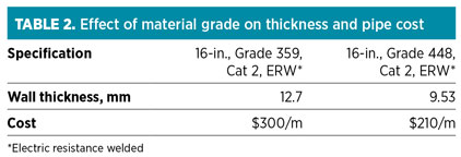
Material. The type of material used in construction has a significant impact on the thickness of the pipeline. Thickness has a reverse relationship to specified minimum yield strength (SMYS). Therefore, if the SMYS is increased, the thickness is decreased. However, the delivery cost of pipe may rise, and the welding of high-tensile material may become more difficult and expensive, as the SMYS increases. Table 2 shows the effect of different material selection on thickness and pipe cost for two 16-in., CSA Z245.1-specified pipes with the same design conditions.
Location class determination. As per American Society of Mechanical Engineers (ASME) standard B31.8,3 location class is a geographic area along the pipeline that is categorized according to the number and proximity of buildings intended for human occupancy and other characteristics. These characteristics are considered when selecting design factors for construction, operating pressures and testing methods for pipelines and mains located in the area.
Location class is a protective measure. As the density and number of people adjacent to the pipeline increase, the probabilities of human injury and property damage increase. Therefore, the determination of the class location is one of the key steps in the pipeline design.
Location class is normally determined by the owner or consultant responsible for preparing the survey drawing. The engineer should carefully review the survey drawing, perform a survey to understand all crossings and neighbors to the pipeline, and then decide the location class.
For example, for a creek or river crossing, a location class of Class 1 is sometimes considered when assuming that there is no occupancy around the creek or river. However, the author believes that a minimum of Class 2 should be considered for such a crossing. The author also suggests labeling the location class on each segment of the pipeline alignment drawings.
Effect of population growth. Population growth causes changes in class location, which require either the installation of new pipe with greater wall thickness, or a reduction of the maximum operating pressure of the existing pipeline, to comply with the updated class location.
For example, if a pipeline is designed in a location that is categorized as Class 1 due to the number of buildings in a particular year, and, 10 years later, the number of buildings reaches 46 or more (which would require a Class 3 categorization), then either the existing pipe would need to be replaced with a pipe of greater wall thickness, or the operating pressure would need to be lowered significantly. This type of risk is considered during the design phase and discussed with the owner.
Design factor (F). The F differs in each code and is the primary factor that restricts the design pressure. In ASME B31.8, the design factor depends on the location class. However, in CSA Z 662, the design factor is constant and equal to 0.80. In the past, the CSA design factor was similar to ASME B31.8 in that it was dependent on the class location or zone. After 1994, the design factor was changed to 0.80, and the location factor was added to the CSA design formula.
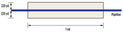
Class location in both ASME B31.8 and CSA Z662 are similar. Included in the formula is an area that extends 220 yd on either side of the centerline of any continuous 1-mi line
(Fig. 1). This area dictates where the existing pipe would need to be replaced with pipe of greater wall thickness, or where the operating pressure would need to be lowered significantly, if the class location were to change. This risk is considered during the design phase and discussed with the owner.
 |
|
Fig. 1. The pipeline location class area shows where existing pipe would need to |
Class locations are used to determine safety design margins in ASME B31.8 and location factors in CSA Z662. They are based on population density. Four different location classes are defined in ASME B31.8 and CSA Z662. However, Class 1 of ASME B31.8 is divided into two different divisions. Division 1 includes locations with F > 0.72 and F < 0.80. Division 2 includes location factors equal to or less than 0.72.
In the thickness formula, design and location factors have a reverse relationship with thickness. After determining the class location, thickness calculations can be performed. Expert engineering judgment and previous experience are required for interpretation of the code requirements.
Aboveground (AG) or buried pipeline. Aboveground pipelines, also called flowlines, include steam, water and gas lines used in steam-assisted gravity drainage projects, to name a few types. The thickness of AG pipeline may be less than the thickness of a buried pipeline for the same design conditions, and calculated based on the same applicable codes and standards.
AG pipeline wall thickness is calculated based on the hoop stress only, but for a buried pipeline with soil-pipe interaction, maximum combined stress (i.e., hoop stress – longitude stress) must be less than 0.9 × SMYS × design temperature.2
Bend method, material and final thickness. Bend wall thickness is calculated alongside straight-run pipe thickness to determine the final pipe wall thickness. The design formula for straight pipe is applicable to bends. However, bending can result in pipe wall thinning, making it economical to consider the same thickness for both bending and straight pipe.
The bending method (i.e., cold bend, hot bend and induction bend) is an important component in the calculation of bend wall thinning. If the bends in a pipeline need greater thickness than the straight portions of the pipe and it is not economical to increase the straight pipe thickness to the bend thickness, then the engineer should try to avoid using transition pieces at both ends of the bends. The bend maker can easily taper the bend ends to match the pipe ends profile.
For example, suppose a pipeline requires 100 induction bends. If the engineer considers transition pieces at the ends of the bends to match to the pipe bevels, then 200 transition pieces should be added to the pipeline, with each bend requiring two transition pieces. The cost of one 30-in., Grade 483, 12.7-mm × 9.51-mm transition piece may reach $10,000; however, if made as a fitting, then this cost can be decreased if the bends are cast from the mother pipe supplied by the owner.
The bend mechanical properties may be changed by bending; therefore, sometimes a higher wall thickness for straight pipe should be considered. For cold bends and induction bends, the engineer should check with the bend maker for the minimum pipe thickness required for the bends. The engineer should consider the same thickness for straight pipe and bends as often as economically and practically possible.
Crossing method. Different types of crossings may lie along the route of pipeline (e.g., railroads and highways, creeks or rivers, etc.). The crossing methods for a pipeline include cut-and-fill, jack-and-bore, horizontal directional drilling (HDD) or another type of trenchless technology.
Open trenching (direct burial) is the preferred method for pipe installation. The pipe can be run through a seal sleeve pipe or installed lower (e.g., two times the normal depth, with higher thickness). The open-trench method creates a significant disturbance, especially in urban areas, and might not be feasible due to difficult ground conditions, existing underground utilities and structures, environmental sensitivities and/or the presence of river, railroad or highway crossings.
Trenchless technologies, such as HDD, may be used instead of open trenching. For HDD crossings, the engineer must consult with the HDD contractor for the minimum required pipe thickness. The author recommends a minimum of Class 2 thickness for creek/river crossings to mitigate the risk of leakage and spill.
Steel pipeline crossing railroads and highways. The engineer should check and confirm that the railroads and highway crossings pass the minimum requirements and calculations outlined in American Petroleum Institute specification 1102 (API 1102). The design conditions and geotechnical and soil information are required for the calculations.
Pipeline buoyancy. Pipelines will “float” to the surface when the weight of the pipe and contents, plus the resistance provided by the backfill, are less than the buoyant force on the pipeline.
If water exists within the trench during construction or operation, it is possible that the empty pipe will float. The buoyancy of a pipeline depends upon the weight of the pipe, the weight of the volume of water displaced by the pipe, the weight of the liquid load carried by the pipe and the weight of the backfill. By selecting a suitable pipe thickness, the engineer can also control the buoyancy of the pipe.
Pipeline design in muskeg. Muskegs are organic soils with high water tables, low shear strengths and low densities. A pipeline in a muskeg can be modeled as a uniformly loaded, continuous-span beam. The maximum bending stress limits should not be exceeded. As the spacing between the buoyancy control tools increases, the pipe bending stress also increases. Muskeg probing to collect more information should be performed during the detailed design phase. The engineer must confirm the pipeline thickness and the MDMT in the muskeg area.
Frost heave and pipeline upheaval buckling. When the soil surface freezes, ice forms within the pores between the particles, often as discrete lenses. Due to the physical nature of water, only part of the water freezes when the temperature falls below the freezing point. Some water remains unfrozen at much lower temperatures. This remaining water migrates in the unfrozen soil toward the freezing fronts, and it continues to move into partially frozen soil. If the surface of the soil is free to move, then it heaves because of the expansion force of water during freezing. This force is normally large enough to lift or dislocate a heavy foundation.
Upheaval buckling sometimes occurs in longitudinally constrained buried pipelines. The driving force for upheavals is the longitudinal force induced by fluid flowing inside of a pipeline. That force is almost always comprehensive. Upheaval buckling begins in an area with over-bend (convex-upward) vertical curves in the pipeline route. If the weight of the pipeline and the uplift resistance of the depth cover are not large enough to hold the pipeline in place, then it will move upward during pipeline operation.
Natural gas, fuel gas, NGL or any other low-temperature pipeline normally operates at a temperature lower than ambient temperature because of the Joule–Thomson cooling effect. This low operating temperature can decrease the soil temperature around the pipeline and cause the water to freeze and heave the soil around the pipeline.
Minimum allowable thickness. Codes and standards, or the owner’s specifications, may have minimum allowable thickness. The engineer should consider the minimum allowable thickness if it is higher than the calculated thickness.
Transportation and storage. The engineer must confirm with the vendor that the pipeline thickness is suitable for transportation and storage, considering the outside diameter and length of the pipeline. It is preferable to use triple-length pipeline to minimize site welding and construction work. However, if the thickness is not carefully selected, then the pipe may be damaged during transportation and storage. Fatigue cracking can happen during pipe shipment, particularly in sea or railway transport. Transit fatigue may result from concentrated stress due to contact with bolts, rivets, bearing strips, seam welds on other pipes, etc.
Liner. The author recommends a minimum corrosion allowance for a pipeline with an internal coat or liner (e.g., those carrying sour water, brackish water, disposal water, etc.) because of the risk of damage to the liner or coating. The thickness of the liner or coating should not be considered in strength calculations for the pipe. The engineer should consult with the liner contractor for the minimum bend radius value.
Hydrostatic test. The calculated thickness should pass the hydrostatic test condition based on the applicable code formula.
Recommendations. The engineer should be familiar with the different causes of pipeline failure and should work to mitigate or transfer these risks during design and thickness calculations. Many factors must be considered during wall thickness calculation and selection, not just the cost or the minimum requirements set in the code wall thickness formula.
Wall thickness can, in some circumstances, threaten the integrity of a pipeline. The calculation and selection of pipeline wall thickness are key areas in the detailed design stage of pipeline projects. Even a small mistake in the selection of the pipeline wall thickness may negatively impact the pipeline’s ability to withstand pressures and meet preset standards and design conditions. GP
LITERATURE CITED
1Canada Energy Resources Conservation Board Directive 56, “Energy development applications and schedules,” 2011.
2Canadian Standards Association Z662, “Oil and gas pipeline system,” 2012.
3American Society of Mechanical Engineers B31.8, “Gas transmission and distribution piping systems,” 2014.
Acknowledgments
The author is grateful to his daughter for her help in editing this article.
 |
Shahab Zardynezhad is a registered senior mechanical engineer in Alberta, Canada with 22 years of experience in large oil, gas and petrochemical projects. He holds a BS degree in mechanical engineering, an MS degree in industrial engineering and an MEng degree in project management.


Comments