
How boil-off gas APC exceeded expectations at an Australian LNG plant
The use of advanced process control (APC) technology on LNG liquefaction trains is well accepted with some of the earliest implementations developed in the late 1990s. Several LNG production sites seeking to extend APC benefits have more recently applied the technology to the LNG storage area, often referred to as the boil-off gas (BOG) system. Depending upon the nature of the overall plant design, the BOG from the LNG storage area can be routed to fuel gas, a domestic gas supply or back into the LNG liquefaction process. A spin-off of these design variants is that the optimization objective can be to either maximize BOG yield (to maximise LNG production), target a specific BOG yield to close a mass balance with minimum losses (e.g., flaring) or minimize BOG yield to unload the refrigerant systems driving the liquefaction process.
Although the nature of these BOG APC applications can be relatively simple (i.e., small in dimensions), the interaction with regular discrete ship loading activities is a challenging complication whereby the duty impacts of cooling down loadout lines and ship storage tanks can return significant load disturbances. In effect, there is some element of sequence logic that must be spliced into the continuous control nature of the APC application to achieve the best outcome.
The ship loading events also add challenge to the automation needs in that there can be a relatively high degree of variability in the following:
- The condition of the ship (i.e., temperature and inerts content in its tanks)
- The manual procedures used by the ship’s personnel (e.g., when to vent BOG back to shore and if/when to utilize the ship’s onboard booster compressor, among others)
- Whether there are leading indicators of the next step in the procedure or not [e.g., some distributed control system (DCS) indication of the loading arms being connected before flow is commenced, a vapor return flowmeter on the BOG from the ship]
- If there are leading indicators available; is there enough time in the ship loading process to take the required action when slowing down the established process is not an option?
One of the primary objectives of the BOG APC is to exploit the surge capacity in the allowable LNG tank pressure range to attenuate the effects of ship loading on the process—this is important to get right for those process designs where the mass balance is closed by either the LNG rundown temperature target or BOG flow return to the condensation loop (both impact cryogenic refrigeration needs).
One important aspect of the LNG tank pressure response is that it is not a perfect battery, where in a perfect battery, the net sum of the work saved (i.e., the reduction in BOG vapor at higher pressure) is expended to re-establish lower pressure conditions for ship loading. This lends the system to optimal positioning of the tank pressure for ship loading as distinct to steady state operation in between ship loading.
APLNG site background. ConocoPhillips operates an LNG facility on Curtis Island, Queensland, Australia on behalf of Australia Pacific LNG (APLNG). ConocoPhillips has successfully applied APC to the two liquefaction trains to deliver operability and economic benefits. Recently, the site turned attention to the development of a BOG APC application to improve the operability and optimization of this part of the process, which has a profound effect on the liquefaction train’s stability and optimization.
At APLNG, the process design is based upon pure component refrigeration circuits driving the liquefaction process, with the LNG storage tank BOG routed back into this process. Accordingly, the primary optimization objectives were to:
- Stabilize the BOG flow back to the liquefaction process
- Minimize the average BOG flow to unload the refrigeration system.
FIG. 1 outlines the nature of the APC system with some duplication deliberately omitted to simplify the diagram. This includes the following:
a. Separate LNG rundown lines from each of the two liquefaction trains join a common header before being split between LNG storage tanks
b. There are two LNG storage tanks
c. Each storage tank has four loadout pumps with individual flow control and recycles
d. There are three BOG compressors (typically two online), each with its own inlet guide vane (IGV) and recycle valve (RV)
e. The BOG return is split before being routed back to the two liquefaction trains.
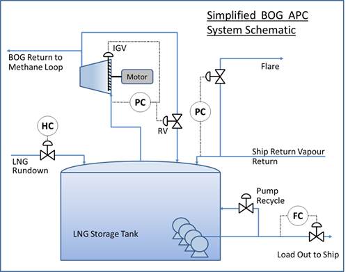
FIG. 1. Simplified schematic of the BOG APC scope.
Compressor control programmable logic controller (PLC) interface. The site is equipped with three BOG compressors of which two are online at any one time. The BOG compressor control and anti-surge protection systems are hosted on a third-party PLC—in effect, a separate process control island from the main process DCS. With some of the original construction project scope not executed, the nature of the PLC control left some optimization opportunity unrealized, including the following:
- Each compressor has its own discrete suction pressure control modulating IGV and RV to achieve a specific suction pressure setpoint and anti-surge margin requirement
- As the suction pressure is common to both online compressors, the combination of these two independent control loops modulating would often skew the set of IGVs and RVs and produce an imbalance in the operation of the two compressors
- This system was unable to determine or pursue load balancing amongst the online compressors
- This system does not naturally deliver the gain scheduling required to provide good control if/when only one (or indeed all three) compressors are online.
While some sites with similar BOG control designs have chosen to eliminate the interaction by staggering the suction pressure setpoints (in effect, scheduling the loads on the compressors), this results in an efficiency loss through the net recycle flow being greater than necessary for the process needs. At the APLNG site, the operators were pursuing a compressor balancing objective by making regular changes on the suction control setpoints to try and balance the operation of the two machines (trading operator workload for inefficiency).
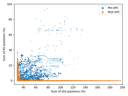
FIG. 2 illustrates the difference in operation sought by coordinating the IGV and RV positioning via the APC—improving efficiency by minimizing the amount of time that additional power was consumed with incremental IGV opening to support additional RV opening. That is, the operators ideally wanted to see either the IGVs or the RVs open but not both simultaneously.

FIG. 2. BOG and IGV coordination.
 While the natural instinct was to collaborate with the PLC control system vendor, travel restrictions during the height of the COVID pandemic and support being on the opposite side of the globe encouraged the approach of developing the APC interface to the PLC control locally. Some initial exploratory step testing using the existing suction pressure controls proved that maintaining these loops as the underlying basis of the APC was not going to be successful. Fortunately, it was feasible to develop a means of getting direct control of the IGV and RV on each compressor while retaining the high frequency anti-surge protection provided by the PLC control.
APC design challenges. Although the APC design is simple on the surface, there are several unique design aspects that are unusual:
- The coupling of the high-frequency compressor control aspects with the much lower frequency needs of the slow acting tank pressure control and optimization brings the need to accommodate a range of potentially competing needs in grossly different timeframes:
- High speed constraint protection for compressor-specific constraints
- The need to stabilize net BOG flow back to liquefaction
- The need to honor the tank pressure range limitations and slowly optimize the tank pressure to the desired target—when one decides that the latter must be done slower than the APC horizon length, this brings some additional customization needs.
- With the manipulated variables being the IGV and RV actuators and the final controlled variable being the tank pressure, there are several challenges with linearity, dynamics and model sensitivity (i.e., the potential for gain ratio issues) that result. This was largely resolved by using the net BOG flow as an intermediate variable to construct a cascade inside the APC design. This approach improves the model robustness and overall APC performance, with the small overhead of some additional mechanics in the model to host the cascade.
- The discrete sequence needs of the shiploading events requires some custom logic to be developed to step the APC through the sequence when reliable leading indicators confirm that a step can progress. Where reliable leading indicators are not available on the DCS, operators initiate the next step according to their procedure. Some of the key objectives of the final solution are:
• More monotonic and lower variance behavior of the main tank pressure control handle (the net BOG flow intermediate variable)
• Early increase of the net BOG flow to attenuate the tank pressure and the APC responses from the initial ship BOG vapor surge seen at the start of shiploading
• Tank pressure positioning after initial cool down and the establishment of maximum LNG loadout flow to accommodate end of loadout disturbances
• Optimizing/balancing of the BOG compressor operation
• Minimizing losses to flare.
APC implementation challenges.
Despite the relatively small dimensions of the APC model matrix (i.e., relatively few inputs and outputs), there were several challenges associated with the implementation of this APC application:
- With no hardwired control links to the PLC for the IGV and RV positions and complexities that would have been required in the PLC supervisory control and data acquisition (SCADA) interface, the risks of completing the initial exploratory step testing (pretesting) were assessed to be too high. Coordinating pretesting between 2x field human-machine interfaces (HMIs) and the control room were also considered impractical. Pretesting would have been preferred ahead of automated step testing.
- A design decision to implement an internal cascade proved useful for dealing with non-linearities in the process, but it did present some unique tuning challenges: The cascade relies on specific care around the tuning used to achieve the desired balance in behavior of the primary vs. the secondary loop in the APC-hosted cascade design.
- Although the APC technology onsite has a proven automatic step testing function, a bootstrap model is required as a starting point. As a result of the issue above (1), this initial pretest model was developed from historian data—this being complicated by the application cause-effect basis being very different to the typical mode of operation captured in the historian. Having said that, a strong process understanding coupled with a plant context facilitated by the internal cascade design enabled the project team to implement a safe and stable bootstrap model with sufficient performance for automated step testing purposes, despite using data that was not exactly fit-for-purpose.
- Site access, plant basis and personnel availability challenges meant that the project team had 2 weeks to complete the following:
- Establish the APC application (based upon the pretest model) and operator HMI
- Establish and validate the APC interface to the PLC control of the IGVs and RVs
- Automated step testing of the process and update the models, as required
- Exercise the constraint control, tune as required and finalize the optimizer design
- Observe ship loading events (every 3 days, on average) and develop the shiploading custom logic and operator procedure to match
- Train the operators on the general APC operation and shiploading procedure.
This is a significant sequence of events to achieve in a single campaign and a testament to the commitment of the project team and the cooperation offered by the site operators.
The project team onsite were able to resolve the challenges associated with the tight timeframe and achieve a good result, which enabled the new APC application to stay online with some minimal tweaks to the shiploading sequence completed over the following few months. Some other minor modifications were made to accommodate single BOG compressor operation to improve the APC uptime during single train operations. Further changes to the shiploading sequence are expected to result from improvements in the manual procedure that are planned.
Project benefits. The outcome of this APC development exercise was very satisfying for the site with a range of benefits realized:
- BOG compressor optimization/balancing benefits. As illustrated in FIG. 2, the APC coordinates the use of the online compressor’s IGV and RV to deliver the global optimum for the system.
- The global optimum results in reduced motor power consumption and reduced compressor IGV and RV (actuator) movement. The reduction in IGV movement has been quantified to be approximately 45%.
- Higher average LNG tank pressure benefits—with the APC demonstrating good constraint control, the operators are comfortable maintaining the more optimal, higher tank pressure in between shiploading events
- The two positional effects stated above also reduced specific BOG flow which marginally unloads the liquefaction refrigeration system. This is illustrated in FIG. 3, which shows the distribution of BOG return flow per BOG in LNG rundown (i.e., BOG out as a fraction of the BOG in). There is a 5.1% reduction (on average) BOG return. The BOG in LNG rundown was calculated based on the pressure drop from liquefaction to the storage tank and the product composition.
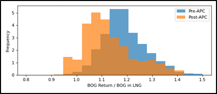 FIG. 3. Tank BOG yield, including shiploading.
 - Smoother load disturbance management during ship loading—the variance of BOG flow back to liquefaction has reduced by 41% as it now tends to move in a more monotonic manner during shiploading events. This greatly helps the stability of the liquefaction trains and their respective APCs to optimize the process. This is illustrated in FIG. 4, where the pre-APC and post-APC data are on the same scale and have had the maximum data points normalized against 1.
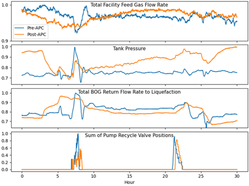
FIG. 4. Key process parameters during a shiploading event.
- The project team’s optimization focus and systematic investigations revealed another opportunity outside of the APC scope, in the LNG loadout pump start-up procedure. The bottom trend in FIG. 4 shows how the original procedure called for all pumps to be brought online at minimum flow (with tangible pump recycle and therefore heat addition to the LNG tank). This procedure was revised to bring each pump sequentially online at a somewhat higher starting flow to minimize the pump recycle. This has reduced the accumulated pump recycle flow for each LNG loadout, resulting in less BOG generation in the LNG tank at a time when total BOG flow is already relatively high.
- Much reduced operator workload has resulted from the development of this APC application relative to the starting basis. The main operator interaction with the system is now initiating the shiploading sequence at the right time ahead of the DCS indicators revealing that this is underway.
To quantify these benefits, the site’s liquefaction APC model gains were used to determine that the reduced BOG flow resulted in a 0.25% production capacity increase for the facility. If the project and ongoing maintenance costs associated with the application are considered, the project had a payback period of less than 1 month and an extremely favorable net present value determination for the APLNG JV.
In conclusion, this APC development is an important step forward in the site’s uptake of APC technology, proving that the benefit:cost ratio of additional applications can be significant once the technology is established onsite through higher absolute value foundation applications. This APC project outcome is an excellent example of how both the development process and the final APC application can achieve the important objectives of:
- An exceptional economic return in terms of production capacity and process efficiency
- Improved operability and reduced operator workload
- Achieving a high acceptance APC solution despite the need for some operator action to initiate the shiploading sequence
- Improved operating envelope adherence and equipment reliability
- Improved process understanding within the organization. GP
ACKNOWLEDGEMENTS
The authors would like to thank Australia Pacific LNG (APLNG) and its shareholders (ConocoPhillips Company 47.5%, Origin Energy Ltd 27.5%, and Sinopec 25%) for their support of this improvement project and their permission to publish this article.
ANDREW TAYLOR is a Director/Principal Consultant at Greenfern Dynamics. He has 30 yr of experience with APC in various industries, including oil refining, LNG production, oil and gas, chemical production and minerals processing. He earned a BE degree in engineering science from the University of Auckland and is a chartered professional member of Engineers Australia.
TOM WILSON is a Senior Process Control Engineer at ConocoPhillips Australia. He has 14 yr of experience in the oil and gas industry. He earned a BE degree in mechatronic engineering from the University of Queensland and is a chartered professional member of Engineers Australia.
ROBERT DAVIS is a Process Engineer working for ConocoPhillips Australia. He has 7 yr of experience in the oil and gas industry working with the Optimized Cascade Process. He earned a BE degree in chemical engineering and is a chartered member of IChemE.
FRANCOIS PIETERSE is a Consultant at Greenfern Dynamics. He has 15 yr of experience with APC in various industries, including oil and gas, minerals processing, and pulp and paper. He earned BE degrees in chemical engineering and process control from the University of Pretoria and is a chartered professional member of Engineers Australia.


Comments