
Sulfur recovery for gas processing plants
Natural gas produced in gas fields is a mixture of hydrocarbons containing hydrogen sulfide (H2S) and organic sulfur species (carbonyl sulfide, COS; carbon disulfide, CS2; and mercaptans, RSH), along with other impurities. The content of the sulfur compounds spans 0.1 vol%–25 vol%, depending on field location and well age. These gases must be removed due to their toxic properties and adverse impacts on the environment. Therefore, gas processing facilities originate gas effluents rich in sulfur species, notably H2S.
Since the sulfur species cannot be discharged to the atmosphere, they must be converted into elemental sulfur and recovered in liquid or solid form by means of a sulfur recovery unit (SRU). Eventually, the residual sulfur species contained in the offgases produced by SRUs are thermally oxidized and released to the atmosphere as SO2 and H2O.
Increased public environmental awareness has led to more severe restrictions on SO2 emissions. In several parts of the world, a sulfur recovery efficiency as high as 99.9+%, which corresponds to 50 mg/Nm3 of SO2 at the stack tip, is required.
Moreover, restrictions are also required on the yearly quantity of SO2 that can be discharged to the atmosphere. This constrains the number of startups and shutdowns a central processing facility (CPF) is allowed in a year. Consequently, SRUs have become vital for the operation of CPFs.
The regulatory framework, the variations of plant throughput required by well production schedules, and the possible presence of BTEX (benzene, toluene, ethylbenzene and xylene) in the SRU feed make the design and operation of an SRU a challenging task for a gas processing facility. A number of variables must be considered including gas pressure, temperature and composition; the quantity of sulfur species (H2S, COS, CS2 and RSH); the economic framework and the location of the gas field.
An SRU encompasses a set of processing units including an acid gas enrichment unit, a Claus unit, a tail gas treatment unit (TGTU), a sulfur degassing unit (DGS) and an oxidizing unit. FIG. 1 shows a block diagram of the sulfur recovery island of an inland CPF processing natural gas from Mediterranean offshore wells.
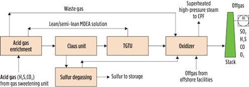 |
| FIG. 1. Sulfur recovery island in a CPF processing offshore Mediterranean gas. |
Acid gas enrichment. A Claus unit must be fed with acid gas rich enough in H2S for the flame of the thermal reactor to be stable. When the acid gas from the upstream sweetening unit contains more than 35 vol% of H2S, it can be handled directly in the Claus reactor furnace without issue.
However, if the acid gas is lean (as often is the case in gas field development projects), then the H2S concentration must be increased above 35 vol% by means of an acid gas enrichment unit. When the acid gas contains 15 vol%–20 vol% of H2S, the enrichment can be attained through a regenerative absorption on MDEA aqueous solutions. (Note: The absorption process on alkanolamines was described in the fifth article of the “Back to Basics” series, published in the September/October 2020 issue.)
Below 15 vol%, formulated alkanolamines or hindered amines can be used to attain an enrichment ratio (the ratio of the H2S content of the acid gas to the Claus unit and the H2S content of the acid gas from the sweetening unit) greater than 3, while maximizing the CO2 rejection (i.e., the CO2 remaining in the offgas).
Alternatively, the desired enrichment can be pursued by recycling to the absorber part of the acid gas extracted from the regeneration tower. In this process setup, the H2S in the feed can be controlled by adjusting the recycle flowrate, as shown in the dotted line of FIG. 2.
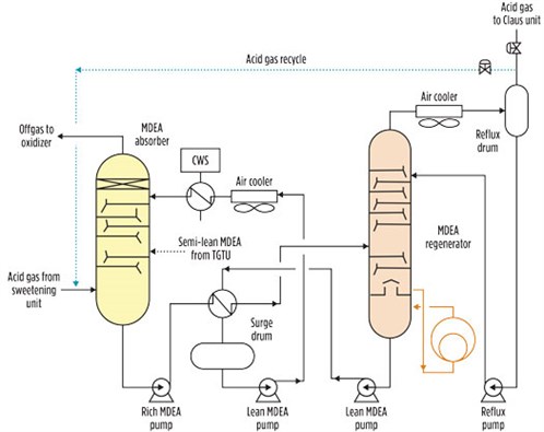 |
| FIG. 2. Acid gas enrichment process flowsheet. |
For large-scale gas plants, this configuration may be expensive due to large volumes of acid gas flows, which translate into large-diameter pipe and large valves.
Claus unit. The function of the Claus unit is to convert H2S into elemental sulfur and water. This is accomplished by reacting H2S with SO2, according to the reversible reaction shown in Eq. 1:
2H2S + SO2 } 3/x Sx + 2H2O (1)
The kinetic of the Claus reaction would be too slow; therefore, it requires either catalysis or high temperature to occur. The SO2 needed by the reaction is introduced into the chemical environment by burning one-third of the fed H2S with atmospheric air through a Claus burner, as shown in Eq. 2:
H2S + 3/2O2 } SO2 + H2O (2)
The oxidation reaction in Eq. 2, being strongly exothermic, develops a temperature higher than 1,000°C if the H2S concentration in the acid gas is greater than 40 vol%.
An industrial Claus unit encompasses a thermal front end and a catalytic end. In the thermal stage, the acid gas and air are admitted into the thermal reactor (TR)—an internally refractory-lined pressure vessel—through a Claus burner. The enthalpy of the process gas exiting the TR at 1,000°C is recovered in the waste heat boiler (WHB) by rising medium-pressure or high-pressure steam. Most of the elemental sulfur formed in the thermal stage is condensed and recovered as liquid.
The process gas exiting the first sulfur condenser contains unreacted H2S, SO2, S, H2O and N2. This stream is directed into a “catalytic assembly” comprising a reheater, an adiabatic fixed-bed catalytic converter and a sulfur condenser. In the catalytic converter, the Claus reaction (Eq. 1) takes place at low temperature, and further elemental sulfur is yielded. To prevent the formed sulfur from condensing inside the catalyst pores, effluents from the previous condenser must be reheated to above the sulfur dewpoint in the reheater. The catalyst of a Claus unit is alumina (Al2O3). When the Claus unit is not integrated with a TGTU based on oxidized sulfur species reduction, and the acid gas contains COS and CS2, a layer of titanium (TiO2) catalyst is placed on the top of the alumina bed. The titanium catalyst promotes organic sulfur hydrolysis to CO2 and H2S.
The recovery of sulfur in a two- or three-stage conventional Claus plant is thermodynamically limited. Typical Claus plant recovery efficiencies are 90%–96% for a two-stage converter plant and 95%–98% for a three-stage reactor plant. Most Claus units are fitted with two catalytic converters (FIG. 3).
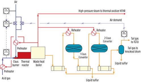 |
| FIG. 3. Claus unit process flow diagram. |
The key process variable of a Claus unit is the “air demand”—i.e., the H2S/SO2 ratio measured at the outlet of the plant. This variable is used to fine-tune the air flowrate to the burner in a way that ensures the optimum operation of the unit.
In a CPF, the acid gas flowrate and its composition can change over time. To provide the Claus unit with the operational flexibility needed to tackle these variations, in addition to the installation of feed and air preheaters to support the Claus operation, the thermal stage of the Claus unit must be designed to accommodate different operational modes, depending on the feedstock characterization.
These modes can be grouped into four categories: straight-through, split-feed, cofiring and fuel-support mode. In the straight-through mode, the entirety of the acid gas and airflow passes through the Claus burner. This mode is set for rich acid gases.
When the H2S concentration falls below 35 vol%–40 vol%, the operation of the Claus unit can be supported by activating the split-feed mode. In this case, a slipstream of the acid gas bypasses the burner and enters an intermediate point of the thermal reactor while the airflow passes through the burner. Since the bypassed acid gas is not involved in the oxidation step, the heat released by the reaction (Eq. 2) is transferred to a lesser mass. This entails a comparatively higher temperature. In this way, the temperature of the flame can be kept at the desired value simply by adjusting the slipstream flowrate. However, when natural gas contains BTEX, the split-feed mode cannot be used because the resulting formation of soot would foul the catalyst converters.
In cases where natural gas contains BTEX and/or when lean acid gas must be processed in the CPF, the operation of the Claus unit can be supported with the cofiring technique. In cofiring mode, a small quantity of a clean fuel gas is added to the thermal reactor to keep the temperature higher than 1,200°C, which is the temperature required for destroying BTEX inside the thermal reactor.
The fuel-support mode is a variationa of the cofiring technique to optimize the handling of very lean acid gas and BTEX bearing gas.
Tail gas treatment unit. The overall sulfur recovery efficiency of a Claus unit is in the range of 94%–98%, depending on the number of Claus catalytic converters. Therefore, Claus offgas still contains a sizeable quantity of SO2, sulfides, COS and CS2. These sulfur compounds must be removed if an overall SRU recovery of more than 99.9% is targeted.
Further removal of sulfur species can be accomplished by complementing the Claus unit with a TGTU. In many CPFs, the TGTU process is based on catalytic reduction of oxidized sulfur species back into H2S by means of a reducing agent, such as H2. The reducing agent is typically produced by burning a clean fuel gas in substoichiometric condition in an inline burner—a reducing gas generation (RGG) process.
SCOT (licensed by Shell), RAR (licensed by Kinetics Technology) and TopClaus (jointly licensed by Worley/Comprimo and Haldor Topsoe) are well-known commercial processes based on RGG. The HCR process (licensed by Siirtec Nigi) supplies reducing gas, exploiting the H2S thermal dissociation (H2S r S + H2) that naturally occurs inside the thermal reactor. In this way, the RGG—which is known to be a source of operational troubles—is no longer required.
In addition to the reduction of oxidized sulfur species, the reduction catalyst also promotes the hydrolysis of COS and CS2. A Claus unit complemented with this kind of TGTU does not need titanium catalyst to destroy the organic sulfur.
A TGTU plant based on the reduction process consists of a catalytic reduction section followed by a quench step and H2S extraction from offgas, as shown in FIG. 4. In this process, the Claus offgas is preheated to 240°C in a gas-gas heat exchanger by means of the high-pressure steam produced in the Claus waste heat boiler. The heated Claus offgas is then charged into a fixed-bed catalytic converter, where the hydrogenation reaction takes place. The offgas in this reactor contains N2, H2S, H2O, CO2 and traces of unreacted SO2. After cooling to 40°C–45°C in the quench tower, the offgas is contacted by an aqueous solution of formulated MDEA, which absorbs the H2S before the effluent is discharged to the atmosphere through an oxidizer (also referred to as an incinerator). The H2S captured by the solvent is stripped in the regeneration tower of the acid gas enrichment section of the SRU and then sent back to the Claus unit, thereby achieving an overall sulfur recovery efficiency greater than 99.9%.
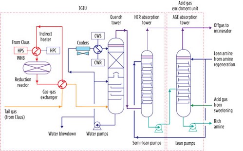 |
| FIG. 4. Integrated tail gas cleanup process representing an integrated TGTU at a gas field development project. |
When only 99%–99.5% sulfur recovery efficiency is allowed, processes based on selective oxidation of H2S to elemental sulfur can be used. The selective oxidation of H2S is achieved by means of a catalyst that does not promote the Claus equilibrium reaction and prevents oxidation to SO2 of the elemental sulfur formed via the reverse reaction of (1, FIG. 3). Other compounds in the process gas, such as COS and CS2, are neither oxidized nor hydrolyzed. Well-known selective oxidation processes include SUPERCLAUS and EUROCLAUS (both licensed by Worley/Comprimo and Jacobs).
Thermal oxidizer (incinerator). The oxidizer/incinerator is the interface between the CPF and the environment. It receives offgases from both the enrichment section and the TGTU. It also receives the sweep air from the sulfur pit.
All these streams still contain “traces” of H2S, COS and CS2 that must be converted into less noxious compounds, such as SO2, CO2 and H2O. Generally, these pollutants are destroyed by means of an oxidation process carried out at temperatures between 450°C and 650°C (up to 940°C when CO oxidation is required by local legislation) before being discharged to the atmosphere.
FIG. 5 shows an example of a thermal oxidizer installed in a large CPF. It includes several elements:
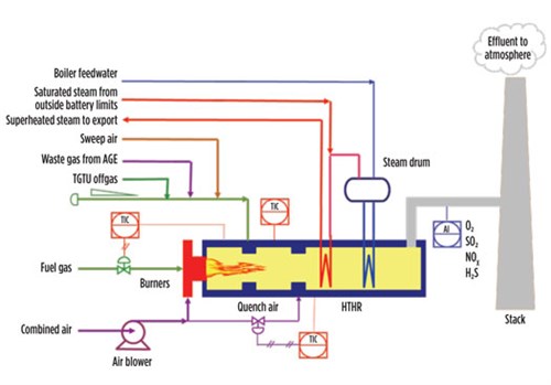 |
| FIG. 5. Integrated thermal oxidizer. |
- A combustion chamber, where a fuel gas is burned with excess air to produce a flue gas hot enough to bring the offgas temperature to the desired level
- An oxidation chamber,where effluents are mixed and thermally oxidized
- A high-temperature heat recovery (HTHR) section, including a waste heat boiler and one or more superheating coils for rising high-pressure steam.
For small-scale CFP, the quantity of high-pressure steam that can be produced may not justify the investment in HTHR. In these cases, the hot effluent is routed toward the atmosphere through the stack after having been quenched with secondary air in the quench chamber of the oxidizer.
Liquid sulfur degassing. Liquid sulfur is formed in the condensers and collected in a pit by gravity. In the condensers, liquid sulfur is in equilibrium with its vapor; therefore, it dissolves a small quantity of H2S. Under the condenser operating conditions, the dissolved H2S reacts with elemental sulfur to form polysulfides (H2Sx, with x > 1). These H2Sx slowly and naturally decompose to form sulfur and H2S. Liquid sulfur, if not degassed, would be risky due to the release of flammable, toxic, corrosive H2S.
In a sulfur degassing system, hot air (sweeping air) can be used as a catalyst for the H2Sx decomposition and as a stripping agent for H2S. The H2S concentration in the degassed liquid sulfur is specified at less than 10 ppmw, which is generally accepted as a safe concentration.
Several commercial liquid degassing systems exist, one of which is the Shell Degassing process. In this system, hot air is bubbled below an open box submerged in the liquid sulfur to create a natural circulation flow that promotes H2Sx decomposition and H2S stripping.
Other processes use hot air as the stripping agent and the promoter/catalyst for the H2Sx decomposition. These processes accomplish the degassing operation in an out-of-pit pressure vessel fitted with mass transfer equipment. Among these are D’GAAS (licensed by Fluor) and SN Degassing (licensed by Siirtec Nigi).
Material and energy integration. An SRU encompasses several intertwined process units, with each one achieving a specific function involving heat exchange and material transformation. The ways in which these specific functions are interwoven affects the service factor of the materials stream and the energy efficiency, which ultimately impacts the economics of a CPF.
In general, the Claus unit produces approximately 2,300 kg–3,000 kg of steam per ton of recovered liquid sulfur. When the waste heat boiler is designed to produce high-pressure steam at 45 barg and greater, this steam can be used not only to supply the Claus captive users (feed preheaters, the reheaters and the plant steam tracing), but also to supply energy to the reducing catalyst of the TGTU through a condensing steam heat exchanger with significant cost advantages over the traditional gas-gas heat exchanger or inline burners.
Moreover, the net valuable high-pressure steam produced in the SRU block can be used by other steam users of the CPF in exchange for the less-valuable steam at 3.5 barg that is needed by the SRU’s MDEA regenerator.
The acid gas load of the MDEA withdrawn from the absorber bottom of the TGTU is in the range of 0.12 mol/mol–0.15 mol/mol; significant pickup capability for a lean MDEA solution remains (note: the load of an MDEA solution is generally 0.45 mol/mol–0.5 mol/mol). This residual pickup capacity can be exploited to reduce the overall MDEA circulation flowrate in the SRU, which entails a further reduction of CAPEX and OPEX due to the reduced duties of the heat exchangers and the electric power requirement of the pumps. This material integration is achieved by feeding the above stream to an intermediate tray of the enrichment absorption tower (FIG. 4), where it is transformed into rich MDEA.
The thermal and material integrations of the processes inside the SRU maximize the thermodynamic efficiency and streams utilization, with economic benefits both in terms of CAPEX and OPEX. GP
NOTE
a Variation introduced by Siirtec Nigi
 |
LORENZO MICUCCI is a Senior Director at Siirtec Nigi SpA. He has more than 30 yr of experience in the engineering and contracting industry, most of which have been spent in the natural gas sector. In 2001, he joined Siirtec Nigi in Milan, where he directed the process design and operations department and the research and development department. During his time as R&D head, three patents have been granted to Siirtec Nigi, two of which have been implemented on an industrial scale. At present, he is the Senior Director of the technology and marketing departments. Mr. Micucci also worked for Saipem (Snamprogetti) as a Plant Designer for integrated gasification combined cycle and gas-to-liquids plants. He holds an MS degree in chemical engineering from the University of Bologna in Italy and is enrolled as a Qualified Engineer in the Register of Milan Order of Engineers.


Comments