
Startup troubleshooting of amine units in LNG export facilities
The production of LNG has gained considerable importance in the past few years because of the energy value contained in natural gas, the ability for export and its lower environmental impact in terms of emissions. In addition, natural gas is seen as a bridge fuel to cleaner energy sources.
LNG production (FIG. 1) begins with inlet separation of contaminants from the feed gas stream, followed by H2S and CO2 removal, water removal, mercury removal and higher-molecular-weight hydrocarbon removal. The gas stream, which is predominantly methane, is then liquefied at –160°C in an aluminum cryogenic heat exchanger. The liquefied product is normally transferred and stored in specialized LNG tanks onsite or on ships prior to delivery to the final destination. All stages of the LNG production process are critical, but the removal of inlet contaminants is one the most important stages as it can affect the entire LNG production sequence at the facility.
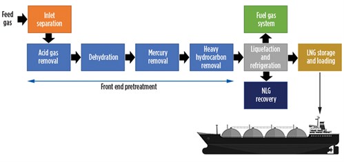 |
| FIG. 1. Simplified block process flow diagram of an LNG production plant. |
Plant startup. Starting up a gas plant, whether for the first time or after a planned or unplanned shutdown, can be a complex (and, in some cases, cumbersome) process that requires many tasks to be performed in a coordinated manner. It is important that a comprehensive procedure is in place and that everyone involved has a shared understanding of the necessary responsibilities.
In a conventional gas plant, several steps must be performed in a cautious manner. Any vessels that were opened during shutdown must be purged to remove air prior to startup. Any process with a heated liquid recycle stream, such as an amine or glycol unit, must be started up and brought in line with normal operating temperatures. Compressors must be started in recycle mode and ramped up slowly. In many situations, systems like these are kept in recycle mode through short shutdowns to avoid longer startup times. When gas is brought in, the process should be opened one valve at a time to make sure that all valves were closed appropriately and that no leaks or failures have occurred. In plants with liquids processing, that portion of the plant must be started up slowly as the front end of the plant is brought online.
Relative to a conventional natural gas processing plant, LNG facilities are even more complex and difficult to start up due to the time required and the sensitivity of the process operations (FIG. 2). While a conventional gas plant can be restarted after a shutdown in a few hours, LNG facilities can require 36 hr or more to return to LNG producing conditions. The primary issue with getting LNG plants running is the very low temperatures required to liquefy natural gas. Even with the front end of the plant running normally, with properly conditioned gas feeding the liquefaction process, the plant may need to recycle gas continuously for a day or more before LNG can be produced and stored.
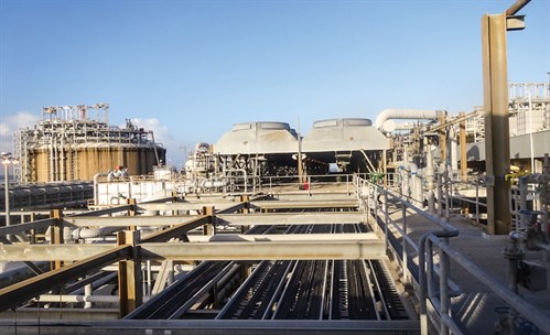 |
| FIG. 2. An LNG production facility. An LNG storage tank can be seen on the left. |
It takes time for these low temperatures to be reached because the main cryogenic heat exchanger (MCHE) must be cooled using mixed refrigerant, and the precooling systems in place (such as propane chilling systems) must be functioning properly to deliver feed gas at an adequately low temperature. Before the cooldown process can take place, the system must be inert with feed gas or nitrogen, and the system must be warmed to remove any moisture.
After the proper conditions are in place at the MCHE and the front end of the plant, MCHE cooling can take place by initially mixing precooled feed gas with warm feed gas to slowly bring the MCHE and mixed refrigerant systems to precooler temperature. The system must be cooled slowly to avoid thermally stressing the system, and it can take up to 12 hr to reach precooler temperatures. After the MCHE reaches precooler temperature, mixed refrigerant flow can be started. Once the mixed refrigerant begins to liquefy, feed flow to the MCHE can commence. The gas exiting the MCHE will not be immediately liquefied, so the effluent must be recycled, flared or sent elsewhere until liquefaction temperature can be reached. The mixed refrigerant composition is varied throughout this process with ethane and propane and, finally, with nitrogen to reach the temperature required for storage. The process described can take more than 10 hr to move from precooler temperatures to liquefaction temperatures.
Common challenges during startup. A number of challenges can occur during plant startup and from a variety of causes. At the front end of the plant, liquids may collect in the legs of piping during shutdown and get pushed downstream all at once upon startup. Slugs of this nature can cause a number of issues, such as foaming, level fluctuations and other instabilities. FIG. 3 shows examples of contaminants present in the feed gas to LNG liquefaction facilities including pipeline corrosion inhibitors, glycols and heavy hydrocarbons. Several other contaminant types not shown here can also be present; the variety and impact of feed contaminants will be the subject of a later article.
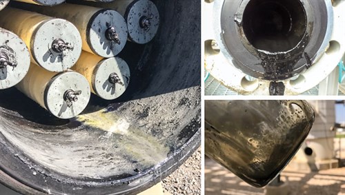 |
| FIG. 3. Example of some contaminants commonly seen in LNG feed gas streams. |
Fluctuations are another issue that often occurs when compressors and other equipment are started and may make process stabilization difficult. Acid gas removal performance often does not meet specifications upon startup due to improper temperature control of the lean amine or feed gas to the contactor, which can cause liquid hydrocarbon condensation.
Several challenges frequently occur in the liquefaction section of the plant, which is much more sensitive to process variabilities. Any previously mentioned issues that occur at the front end of the plant will affect the liquefaction process in some way. If the issue is severe, it can require a complete restart of the cooldown process, resulting in a day or more of lost production. The case study presented in the following section details challenges in achieving stable operations at the front end of an LNG production facility to properly start up the liquefaction stage.
If foaming occurs in the amine unit, then feed gas flow to the liquefaction process may be disrupted or stopped entirely. While conventional gas plants can often endure some foaming events without necessarily affecting CO2 levels, LNG facilities often cannot because of more stringent specifications. Small foaming events that might slightly affect treating performance can still cause the treated gas to miss specification, meaning it cannot be sent to liquefaction. Gas flow to liquefaction may also be affected if the dehydration or mercury removal stages cannot remove contaminants to the required levels.
Any scenario causing flow disruption to liquefaction can result in delayed or discontinued cooling of the MCHE and mixed refrigerant systems. Depending on how long flow is disrupted, the entire cooldown process may need to be restarted if temperatures cannot be maintained in the interim. This chain of events can result in a cascade of delays; therefore, effective troubleshooting of the front end of the process must take place to ensure stability before restarting. This is critical for the liquefaction stage to start up without disturbance.
One of the main challenges with LNG production startup is maintaining the consistent and stable operating parameters required to move from startup conditions to production. Control loops and other systems in place for correcting flow or temperature are often programmed too aggressively or conservatively to adequately respond to fluctuation, or they are manually adjusted in an improper manner. A common issue with improperly tuned control loops is a cascade of fluctuations that results in process instability and inefficient cooling of the liquefaction stage. Several steps in the cooldown process require precise and subtle modification to process setpoints, and significant cascading deficiencies can occur if one parameter is even slightly misadjusted. For example, if the mixed refrigerant composition is not adjusted properly then the MCHE can cool too quickly, causing materials thermal stress; or the temperature profile can become imbalanced, resulting in overcompensation from other control loops and exacerbated imbalances.
A common issue with cold restarts during commissioning is the presence of residual contaminants in the liquefaction stage. Any dust, moisture or other contaminant in piping or vessels that is not removed prior to startup can affect the liquefaction. Solids present in the process that reach the MCHE can act as nucleation points for freezing if moisture is present, or they can simply foul the exchanger. The MCHE is sensitive to fouling and freezing, resulting in drastic reduction to heat transfer performance and, potentially, eventual failure.
Case study. A North American LNG production facility was experiencing several difficulties in the amine unit during the initial startup and commissioning phase, such as foaming and process fluctuations. Several events in the amine unit contactor occurred, including high-differential pressure spikes, a rapid loss of contactor level and cascading effects throughout the unit. Fluctuations occurred in amine solvent flow and other parameters throughout the unit, leading to instability and an eventual shutdown. Blockage of strainers and problems in the regenerator reflux line also occurred.
The inability to continuously operate the amine unit with adequate treating and stability for more than two days prevented startup of the downstream liquefaction process. The system could not be operated long enough to reach sufficiently low temperatures to produce LNG, and temperatures increased again when amine unit instability forced a shutdown, erasing any progress made.
The plant startup was postponed for unrelated reasons, but the commissioning team anticipated that the same issues would occur and took several precautions for the next startup attempt. The amine unit was chemically cleaned prior to the next startup, and several samples collected during and after the initial startup attempt were analyzed. The author’s company was brought onsite to assist with the startup process, test the feed gas for suspected contamination and troubleshoot amine unit foaming and instability.
Preliminary testing and onsite evaluation. Prior to onsite testing and troubleshooting, several preliminary evaluations and analyses were performed. Materials such as filters, coalescers and activated carbon used in the amine system were tested for chemical compatibility with the amine solvent. It is often the case that materials used in the amine system leach contaminants or otherwise adversely affect unit operation. All of the feed gas coalescers, amine filter elements and activated carbon canister materials were found to have incorrect chemical compatibility with the amine solvent or feed hydrocarbons, leading to foaming and, therefore, solvent losses due to carryover.
Gravimetric testing was performed in several locations in the amine unit while onsite to quantify suspended solids in the amine solvent. Significant solids content was found at the inlet of the contactor downstream of the high-pressure pump and amine carbon bed, and an analysis of these solids identified them as carbon fines. The carbon bed was then bypassed for 24 hr, and the solid content decreased substantially. The color of the amine went from a darker tint to the clear tint observed in the rest of the amine.
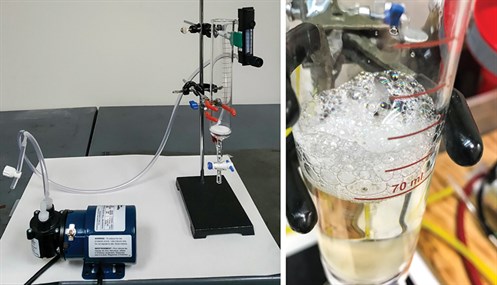
Feed gas contamination testing was performed continuously during onsite work to determine if startup foaming challenges were due to surfactant contaminants present in the feed gas stream. This testing was completed using two testing units that use high-pressure housings equipped with proprietary coalescing media that is designed for the capture and separation of liquid contaminants and aerosols in the gas stream. FIG. 4 shows the dual-stage testing system setup. A water wash injection point was installed between the two units to process a slipstream at the inlet to the amine unit feed gas coalescer. Another testing unit was used at the outlet of the coalescer to determine its liquids removal efficiency. Both testing units were operated for more than two weeks continuously, and no liquids accumulation was observed in either system.
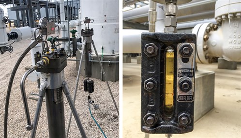 |
| FIG. 4. Example of a feed gas testing unit setup, showing liquids accumulation. |
The water wash injection was conducted to contact the gas with water and extract any soluble contaminants into the water for further analysis. Water was injected into the inlet of the testing unit at the inlet of the coalescer, and the water was then coalesced and drained from the testing element into the sight glass, where it was collected and added back to the water injection pump suction. This process was repeated 10 times to saturate the injected water with as much soluble contamination as possible to allow for effective analysis.
General troubleshooting and evaluation of historical data and current conditions were also performed. Several observations relevant to plant startup challenges were made:
- Methanol ingression (likely intermittent): Methanol was detected in rich amine and reflux water samples. Methanol can cause flashing issues and temperature excursions in the regenerator, and it will reduce surface tension of the amine solvent, making the solvent more susceptible to foaming.
- Logic deficiency in flash tank level: Flow from the flash tank was set up to choke to maintain a certain level. This setup deprived the regenerator of the necessary flow required for stable operation.
- Carbon bed sizing and evaluation: The carbon bed was sized adequately for a very low amine flowrate; contaminant removal performance will be poor at higher flowrates due to insufficient contact time. The canister design of the carbon bed was also not ideal for a number of reasons. Canister materials, as well as the carbon product itself, were incompatible with the amine solvent and increased foam tendency.
- Molecular sieve dust solids: Solids analysis showed that the molecular sieve dust filter was carrying over dust to the amine unit. This was caused by the recirculation of treated gas from the dehydration stage to the front end of the facility during startup mode. This also demonstrated the ineffectiveness of the dust filters downstream of the molecular sieve beds. Improved filtration and minimized recycling were necessary action items.
- Amine solvent concentration fluctuations: Makeup water was added manually to the amine surge tank based on regular amine strength testing. Adding large amounts of makeup water to the surge tank, which does not have proper mixing capability, likely resulted in fluctuations in amine solvent concentration throughout the amine solvent circuit. A low amine solvent concentration is much more prone to frothing leading to foaming. The inlet nozzle for the surge tank was directly above the outlet nozzle, essentially routing a large portion of the added makeup water directly into the process (instead of properly mixing with the amine solvent in the surge tank). Slower rates of makeup water addition to the unit should be used to avoid diluted amine solvent slugging into the recirculating process.
- Incomplete unit rinse prior to startup: Certain areas, such as the reflux, may have had residual contamination present. Residual contaminants, potentially from the cleaning itself, may have remained in the system and were removed in the strainer. When cleaning a process unit such as an amine unit, a foam test of the final rinse liquid is necessary to ensure no foam formation prior to loading the new amine solvent.
- Inefficient antifoam use: Testing showed that the antifoam product used at the plant was only marginally effective in reducing foam tendency and stability. The use of an ineffective antifoam during foaming events will not eliminate foam quickly enough, often causing a unit shutdown. A more effective product was identified during onsite testing.
- Feed gas-amine temperature differential in the contactor tower: The difference in temperature between the feed gas and the amine entering the contactor was lower than recommended. If the feed gas temperature exceeds the lean amine temperature, then hydrocarbon condensation can occur.
- Rapid increase in feed gas flowrates to the unit: The gas flowrate to the amine unit was increased too rapidly at times during the startup procedure. Gas flow should be increased in small increments at a time, and it should be increased only every half hour, at most. The gas flowrate should not be increased until the process stabilizes and accepts the new conditions adequately. The increase should also depend on the size of the contactor. For smaller amine units this process is even more delicate, as smaller towers can be much more sensitive to any change, leading to upsets like foaming.
Sample analysis and testing. From the analysis and foam testing of the feed gas water wash sample, it was determined that a small but manageable amount of surfactant contamination was present in the feed gas stream. FIG. 5 shows the surface tension of the water wash sample compared to pure water, water with methanol, water with surfactants, and hexanes. It can be observed that surfactant contamination significantly reduces surface tension, as does methanol contamination (to a lesser extent). The surface tension depression with methanol at much higher concentrations is not as large as with surfactants at low concentration, because methanol is not a surfactant but changes the properties of the solvent by weakening intermolecular forces. Hexanes presented the lowest surface tension because they do not have appreciable intermolecular forces. No hydrogen bonding and only weak Van Der Walls forces are present. This is one of the reasons why hydrocarbons will, in certain cases, facilitate foam formation by lowering surface tension, but they will not stabilize foam.
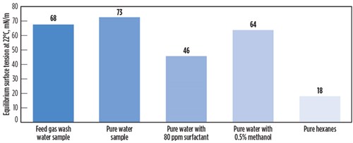 |
| FIG. 5. Surface tension of selected liquids and liquid mixtures. |
Foam testing was performed using a standardized test with a specially designed apparatus, as shown in FIG. 6. The test apparatus consists of a glass column equipped with a porous glass frit for homogenous gas dispersion. Air is pumped into the inlet across the porous glass frit and into the cylinder section, where the sample is added. The flow of air is metered into the system so that results are reproducible and consistent throughout each test. The air is introduced for a set period of time, and the foam height is measured when air flow is ceased. The time it takes the foam to break is then recorded.
 |
| FIG. 6. Assembled foam testing apparatus (left); amine solvent with foam formation (right). |
Foam testing of several samples collected throughout the plant showed a number of anomalies. Foam tendency increased at the carbon bed outlet, suggesting that the carbon bed was spent, had the incorrect carbon or possibly was leaching contaminants. High variability in foam tendency was also observed among amine solvent samples at various sampling locations and times, suggesting fluctuations in the process. Samples of amine solvent indicated low foaming tendency during routine checks, but when tested during high-contactor-differential pressure events or foaming signals in the regenerator, foaming tendency was moderate to high. The reflux water sample had high foaming tendency, which may have led to changes in the amine solvent composition. The amine unit treated gas and the molecular sieve inlet separator liquids, which were both routed back to the amine unit, also had very high foaming tendency. The number of samples with high foam tendency and their various sources showed that a number of factors likely contributed to startup foaming challenges.
Process simulation. After onsite work was completed, process simulations were performed on the amine unit contactor to determine if the contactor was experiencing weeping or operating in a spray flow regime. Weeping occurs when there is too much liquid on each tray and amine spills downward, affecting acid gas removal. In a spray flow regime, however, there is insufficient liquid on each of the trays to handle the high vapor rate, resulting in physical entrainment of droplets of amine above the trays that could easily travel to the tray above, overhead or even over the weir to the tray below. Further into spray mode the liquid may not even settle upon the trays, but instead flow along with the vapor.
The simulation results indicated that the contactor was in fact in a spray flow regime. This undesirable flow regime was likely inadvertently achieved by reducing the amine solvent flowrate as a response to the lower-than-anticipated CO2 levels. The rationale for reducing solvent flow based on CO2 levels alone is not an accurate protocol, as mass flowrate of the gas phase should be considered in conjunction with CO2 levels, contactor design and tray ratings.
Spray flow usually happens at the top trays in an amine unit contactor. This phenomenon occurs when low liquid loads of amine solvent on trays lead to liquid aerosolization into the treated outlet gas. This causes constant low-to-medium levels of amine solvent losses that can, in many cases, go unnoticed. To move the flow regime from spray mode to froth mode (to the left of the spray regime in FIG. 7), it was recommended to increase the amine solvent flowrate and raise the liquid load on the contactor trays. FIG. 7 shows a diagram of flow regimes in a trayed tower based on liquid and vapor flowrates. The froth regime area represents the most ideal conditions for a tray-based amine unit contactor.
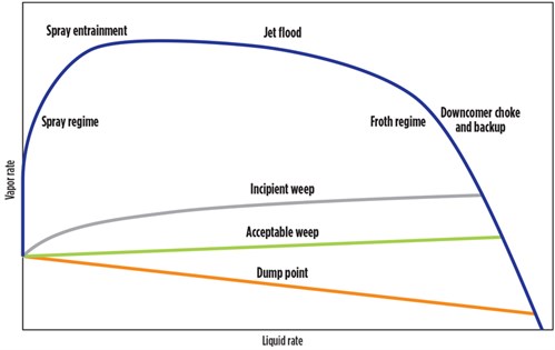 |
| FIG. 7. Tray flow regime diagram. Diagram adapted from Kister, H. Z., Distillation Design, McGraw-Hill, 1992. |
Evaluation of the regenerator was also performed and revealed that a flow control valve in the reflux overhead for manual regenerator operation was not present, which may have led to instabilities. The regenerator, when operating in automatic mode, has a smoother and more effective control because more than one variable is manipulated at a time. Additionally, no temperature control was present in the reflux overhead.
Findings, recommendations and remarks. After assessing each aspect of the process related to startup, it was concluded that no single factor could be resolved to allow the plant to start up successfully. A number of areas were identified that contributed to foaming, process fluctuations and other detrimental effects that hindered the plant from reaching its design operating conditions. The design of the contactor tower at the amine unit was sensitive to foaming and fluctuations compared to other contactors. Inadequate operational control capabilities, insufficient lean amine flowrate to the contactor causing a spray flow regime, low-to-moderate levels of contamination (including methanol ingression), and an ineffective activated carbon were all major causes of amine unit shutdowns. The root causes of foaming were likely low-to-moderate levels of gas-phase contaminant ingression with the feed gas, recycled streams from downstream processes and materials, and chemical incompatibility with several materials. Contaminants exposed to regenerator temperatures may also have formed more aggressive foam promotors, leading to high foaming tendency in the reflux accumulator.
In any case, several actions taken in parallel were necessary to successfully combat the startup challenges. The plant was eventually able to start up and operate at design conditions after addressing the concerns identified in this evaluation. Automated control schemes and better operating practices, as well as compatible materials, were used to stabilize the process and remove contaminants (some promoting foam formation). New carbon materials, antifoam and amine filters with no adverse compatibility effects were recommended.
A more coordinated and careful approach to startup was taken. The front end of the plant was slowly and cautiously started, in terms of feed gas flow introduction, after new control solutions were installed. LNG processes can be difficult to operate and maintain, and startup can be even more cumbersome due to the number and variety of tasks involved. Addressing each task in a systematic and organized way is vital for an on-time and on-specification LNG production startup. Despite all the changes made, the most important factor in achieving stable startup operation was a unified and communicative environment among operators and engineers at the plant. Situations may arise unexpectedly, but proper training and communication can help resolve upsets before they grow out of control. GP
 |
DAVID ENGEL has more than 25 yr of industrial experience in a variety of chemical engineering and chemistry areas. He is the inventor in 21 US patents and the author of a number of technical and scientific papers. Dr. Engel has developed business and technology for Eastman Kodak, Eli Lilly, Pentair, General Electric and Sulphur Experts worldwide. He has specialized in chemical engineering, process chemistry, optimization and contaminant removal technologies. He is the Managing Director of Nexo Solutions and the Technology Leader for Exion Systems. He holds a BS degree in industrial chemistry, a MS degree in chemistry and a PhD in organic chemistry. He is also Six Sigma and Project Management certified. Dr. Engel is President of the American Filtration Society, Southwest Region; and a member of the Gas Processors Association Technical Section M, in addition to a member of the boards of directors at several companies.
 |
CODY RIDGE is a Lead Process Engineer at Amine Optimization Company and a Chemical Engineer from Texas Tech University in Lubbock, Texas. He is responsible for field engineering and technology development with Amine Optimization. Mr. Ridge has worked as an operator and process engineer in the Permian Basin.
 |
SCOTT WILLIAMS is a Process Engineer at Amine Optimization. He has industry experience in a number of projects in oil and gas, petrochemical, chemical and water treatment applications. As part of the Amine Optimization engineering group, Mr. Williams is responsible for technical design and solutions development in engineering and technology applications. He also provides support for analytical and specialized service projects. His recent work has been focused on amine unit contamination control, process stability and energy reduction. Mr. Williams holds a BS degree in chemical and biological engineering from the University of Colorado at Boulder.


Comments