
Natural gas phase separation and mercury removal
Gas processing plants are integral parts of the natural gas value chain. They are generally located close to production sites, which are typically constituted of clusters of wells scattered across gas fields. The fluids coming out from these wells are “harvested” by means of gathering systems.
The wellstreams collected by the gathering system are multi-phase streams comprising gas, liquid slugs of brine or free water, liquid hydrocarbons, corrosion inhibitors, methanol and other wellbore fluids. Since the produced brine and produced water are corrosive, since less energy to move separated single phases is required, and since processing gas, water and condensates separately is easier and less expensive, the phase separation of wellstreams is performed both in the proximity of wells and at the CPF front-end, where it is generally more convenient to remove Hg.
Mercury (Hg) is sometimes contained in trace levels in natural gas. It must be reduced to a parts-per-billion level to produce salable gas or feedstock for liquefaction plants. This article, the fourth in the “Back to basics” series, discusses the key fundamentals of phase separation and mercury removal.
Phase behavior. Fluids produced at the wellhead are classified on the basis of the reservoir temperature (T), pressure (P) and thermodynamic properties of the hydrocarbon mixture. As formation fluids exit a reservoir, enter the wellbores and travel up to the producing string to the wellheads, both P and T decrease.
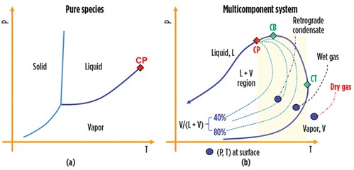
The phase change natural gas undergoes following these variations in T and P define the character of the fluids and provide the data needed to design the phase separation systems. For a given P, the vapor of a pure component condenses at unique constant temperature, and the function P = f(T) draws a vapor pressure line in the T–P diagram, as shown in FIG. 1A. Instead, for a multicomponent system, the vapor pressure line becomes an envelope, or saturation line, comprising the locus of bubble points (to the left of the critical point, or CP) and the locus of dewpoints (to the right of the CP). The envelope circumscribes the area where liquid and gas phases coexist in equilibrium, as shown in FIG. 1B.
 |
|
FIG. 1. Pure component system vs. multicomponent system. |
A phase envelope has three key points:
- The critical point that identifies the conditions at which liquid and gas become indistinguishable
- The cricondenbar (CB), the highest pressure at which liquid and vapor can coexist in a mixture
- The cricondentherm (CT), the highest temperature at which the two phases can coexist in a mixture.
For a given T between the CP and the CT (i.e., for a T falling inside the highlighted band in FIG. 1B), liquid forms when the gas pressure decreases. However, with continued pressure decrease, a point is reached where the liquid re-evaporates and disappears when the pressure reaches the dewpoint curve from above. This phenomenon is known as retrograde vaporization. Note: The CP falls to the left of the CB for natural gas. Moreover, the CB can be greater than the CP.
These three points and the reservoir temperature and pressure location in the T–P diagram relative to the phase envelope define the type of fluid produced at the surface. When the reservoir (T, P) point is located to the right of the CT, an isothermal production path does not cross the phase envelope, and no liquid emerges at the surface. In this case, the natural gas flowing out of the wellheads is termed dry gas, and no liquid hydrocarbon will be collected in phase separators. In practice, the dry gas is rarely produced at the wellhead, and the term “dry gas” conventionally designates a natural gas containing less than 2 gal/1,000 ft3. In the majority of cases, T, P at the wellhead falls inside the liquid-vapor area and the wet gas comes with condensate, as shown in FIG. 1B.
When the temperature falls between the CB and the CT, a retrograde condensation takes place. In this case, the reservoir is classified as a condensate reservoir, and the produced fluid is often referred to as gas condensate or retrograde gas. The relative amounts of liquid and gas produced at surface may be sizable. TABLE 1 provides points of reference regarding wellhead fluids characteristics.
 |
As can be seen, retrograde gas contains a considerable amount of liquefiable hydrocarbons and is rich in condensable gases. A stepwise reduction of the pressure is a means to increase the recovery of condensate. The overall amount of produced condensate depends on the number of stages included in the separation arrangement and the operating pressure of each stage.
It is generally accepted that for retrograde gas, two stages of separation maximizes the condensate production. The pressure (40 ÷ 80 bar) of the first separation stage is normally dictated by the gas transmission line and the operating characteristics of the wells. The optimum pressure for the second stage depends on the P set for the first stages.
Most oil-bearing and/or gas-bearing rocks also contain water; therefore, produced water comes together with gas at the wellhead in almost all gas extractions. Regardless, the amount of produced water, which can vary widely in different places or over the lifetime of a single well, must be separated from the hydrocarbon streams in a phase-separation unit so that less-expensive materials of construction can be selected for downstream unit operations.
Wellstream separators. Separators are pressure vessels used to remove natural gas from liquids at a specified pressure and temperature. These items can be oriented either vertically or horizontally. The vertical items are preferred for separating liquids from mixtures with high gas-liquids ratios, while horizontal vessels are used for separating large volumes of gas and liquid or when a large amount of dissolved gases are present in the liquid phase.
Stable and efficient gas-liquids separation is achieved in three distinct stages, as explained in the following sections.
Primary separation. Primary separation is for removing the bulk of the liquids in the inlet stream. This separation is achieved by exploiting the differences in density of the phases to be separated. The different densities translate into different momentums (mass multiplied by velocity).
Consequently, following the impingement against a diverter, liquid portions cannot turn rapidly due to their much greater momentum relative to the vapor phase, and separation occurs. Momentum is the main principle underlying the bulk separation of large liquid volumes that are randomly formed (slugs) in finger-style slug catchers.
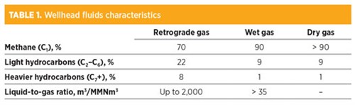
FIG. 2 shows a slug catcher comprising a manifold system of pipes (fingers). This kind of separator is preferred for high-pressure separation, as “small” pipe diameters require lower metal thickness, thereby resulting in a lower cost relative to a single horizontal vessel. However, the finger-style slug catcher requires a large footprint. For example, the slug catcher shown in FIG. 2, designed for a small gas field (7 MMsft3d) in the Caucasus region, is 70 m long.
 |
|
FIG. 2. Finger-style slug catcher. Image courtesy of Siirtec Nigi SpA. |
Secondary separation. The main separation principle underlying this stage is the gravity settling after the velocity of the phases has been reduced to the point where the gravity force prevails on the opposing drag force so that liquid droplets fall into the liquid accumulator section of the separator.
For horizontal vessels, the minimum length is calculated by assuming that the time for the gas to flow from the inlet to the outlet is the same as for the droplets to fall by gravity from the inlet nozzle to the liquid surface. Generally, the fraction of the total vessel cross-section made available for the flow of gas is around 0.5. In this scenario, most liquid droplets separate from the gas.
Moreover, in three-phase separators, to promote either dissolved gas disengagement from liquid and liquid-liquid (oil-water) separation, the holdup time for the liquid held in the accumulator section of the equipment is set for 3 min–30 min, depending on liquid density and temperature. The greater the T, the easier the separation due to the lower viscosity and the lower holdup time. Conversely, the separation becomes more difficult with increasing density, and higher residence time is required.
For two-phase separation, 1 min–4 min of holdup time is specified to ensure gas disengagement from liquid.
Stage 3: Mist extraction. In this stage of separation, small droplets (normally down to 10 microns in diameter) still entrained in the gas phase are removed by coalescing before the gas leaves the vessel. Several designs are available for the mist extractor: knitted mesh pad, vane packs, swirl-tube decks, cyclone separators and candle filters. The knitted mesh is the most-used mist extractor in phase separators.
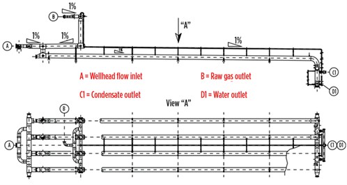
FIG. 3 shows how the three steps of the separation process are arranged in a horizontal separator. The primary separation is, in this case, achieved by allowing the fluid to impinge against a plate perpendicular to the flow direction. In this way, the horizontal component of the velocity vector is nullified, and liquid chunks will fall into the liquid accumulator section of the separator.
 |
|
FIG. 3. Three-phase separator. |
FIG. 3 shows how a calming baffle has been provided to reduce turbulence and increase the separation efficiency. The capacity of the liquids accumulator must be set so that the velocity profiles result in minimum disturbance of the liquids from the gas stream, and to provide the necessary retention time for efficient separation of the gas rising from the liquids and the separation of water from condensate.
To ensure proper operation, phase separators must be fitted with pressure and level control loops (two for a three-phase separator), and field instruments including a level gauge, a pressure gauge, a thermometer well, safety valves, and anti-vortex baffles (for avoiding liquid rotational flow, which could cause undesired gas entrapment in the liquid).
Mercury removal. Hg is often found at trace levels, predominantly in its elemental form, in natural gas. Depending on the reservoir location, its concentration spans from the barely detectable 0.01 µg/Nm3 up to 5,000 µg/Nm3. Hg is toxic; according to ACGIH’s 2019 Guide to Occupational Exposure Values,1 its threshold limit value (TWA) is 0.025 mg/m3.
As Hg has a relatively high vapor pressure (0.26 Pa at 20°C), it becomes distributed throughout the processing facilities and in plant effluents. In particular, it can be absorbed on the amines used for gas sweetening and by the glycols used in dehydration units. Consequently, this toxic metal gives rise to an environmental hazard when found in the dehydration vent gas and in the amine regeneration overhead offgas.
Moreover, Hg can cause serious corrosion problems during shutdown, startup and maintenance operations of gas processing units with cryogenic sections. Hg forms amalgam with the aluminum forming the cryogenic heat exchangers. In the presence of water or air, the amalgam reacts quickly to form alumina, elemental Hg and hydrogen, causing damage to equipment.
Hg may also give rise to metal embrittlement in the absence of water, which results in intragranular cracks in the construction material. This phenomenon was the root cause of the catastrophic failures at the Skikda LNG plant in Algeria in 1975, and at the Moomba gas plant in Australia in 2004. An Hg limit of 0.01 µg/Nm3 is now generally set for the feedstock of a liquefaction plant.
The technology for removing Hg from natural gas is based on either a chemisorption or a physisorption process, in which the gas continues to flow through a fixed bed of sorbent media consisting of a reactive chemical species supported on inert materials. Among these processes, non-regenerative and regenerative processes can be distinguished.
Non-regenerative technologies. In non-regenerative processes, the sorbent must be disposed of when it becomes saturated with mercury. This category includes:
- Activated carbon impregnated with sulfur or metal sulfide. The former requires the gas to be dry and free of C5+. The latter can be used for both dry and wet natural gas. Hg is retained as mercuric sulfide (HgS) formed by a reaction with metal sulfide: Hg + MexSy ≥ HgS + MexSy-1. It should be emphasized that the disposal of exhausted activated carbon is difficult, since landfilling is no longer permitted in many parts of the world. The activated carbon is typically loaded into fixed-bed reactors (axial or radial flow design). The latter is preferable when the pressure drop through the bed must be minimized. These reactors can be arranged according to a lead-lag setup, which ensures long service with minimal need for operators.
FIG. 4 shows a typical non-regenerative sorbent process based on the lead-lag concept. In this process diagram, the gas passes through the fixed-bed adsorption bed (A). The Hg-free raw gas from (A) heads to the second bed (B), which acts as a guard. Regardless of its actual saturation, after a pre-set period (1 yr, for example), (A) is taken off operation for the activated carbon to be replaced; meanwhile, the raw gas is diverted to (B), which becomes the adsorbing tower. Following the fresh sorbent loading, tower (A) is reinserted into the production cycle, this time as the guard bed shielding the downstream items from potential upset of (B). -
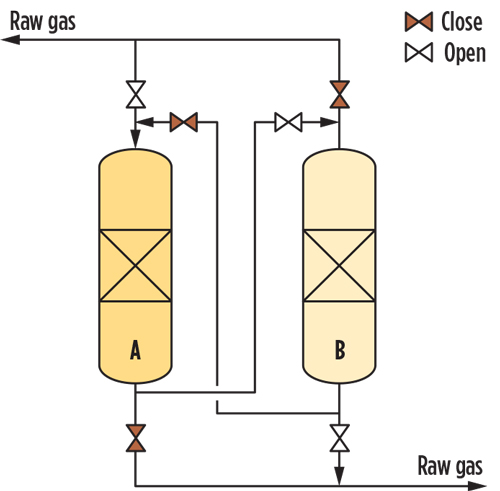
FIG. 4. Mercury removal unit.
- Metal sulfide supported on alumina. The chemical process mechanism is much the same as that of activated carbon. However, this kind of sorbent can also be used for wet gas or for gas containing heavy hydrocarbons. Moreover, the disposal of the exhausted bed is less difficult compared with the activated carbon, as it can be recycled through smelters.
Regenerative technologies. In these cases, the sorbent material is silver supported on the molecular sieves (or molsieves) used for the natural gas dehydration process, which will be discussed in a future “Back to basics” article. Hg reacts with silver to form an amalgam. During the regeneration of the molsieves, Hg is transferred to the regeneration gas; it can be removed by condensation and recovered as a separate liquid stream. This process can be used in a standalone unit or in combination with a non-regenerative mercury removal unit (MRU) located on the regeneration gas circuit.
The silver molsieves, adsorbing Hg and water simultaneously, can replace part of the dehydration-grade molsieve used for drying feedstock for an LNG plant. Since it is placed in an existing vessel, no additional capital is required. However, water that is removed from the gas and collected in the knockout drum of the regeneration circuit may contain a sizeable quantity of Hg that must be removed by an additional unit.
The technology selection has an impact on where the MRU is located within the CPF. Since sulfur-impregnated active carbons are vulnerable to moisture and heavier hydrocarbons, this system must be located directly after the sweetening and dehydration units. However, in such cases, due to its “high” vapor pressure Hg might be found in the offgases from the acid gas removal unit and/or the dehydrator vent gas, which gives rise to environmental hazards.
Furthermore, since Hg is prone to adhering to the metal surface of piping and equipment, health hazards may eventually develop for operators and maintenance workers. The considerations outlined here suggest that the preferred location for the MRU is the raw natural gas stream, directly after the phase separation unit. GP
LITERATURE CITED
- ACGIH, 2019 Guide to Occupational Exposure Values, 2019: https://www.acgih.org/forms/store/ProductFormPublic/2019-guide-to-occupational-exposure-values
 |
Lorenzo Micucci is a Senior Director at Siirtec Nigi SpA. He has more than 30 yr of experience in the engineering and contracting industry, most of which have been spent in the natural gas sector. In 2001, he joined Siirtec Nigi in Milan, where he directed the process design and operations department and the research and development department. During his time as R&D head, three patents have been granted to Siirtec Nigi, two of which have been implemented on an industrial scale. At present, he is the Senior Director of the technology and marketing departments. Mr. Micucci also worked for Saipem (Snamprogetti) as a Plant Designer for integrated gasification combined cycle and gas-to-liquids plants. He holds an MS degree in chemical engineering from the University of Bologna in Italy and is enrolled as a Qualified Engineer in the Register of Milan Order of Engineers.


Comments