
LNG plant optimization with ammonia precooling
N. Gnanendran and J. Baguley, LNG Ltd., Houston, Texas
The selection of liquefaction technology and refrigerants plays a key role in optimizing process efficiency while minimizing costs in LNG plants. Large baseload LNG export facilities incorporate a precooling refrigeration cycle as a proven means to increase both overall liquefaction energy and cost efficiencies.
Historically, propane has been selected as the precooling refrigerant since it was available for extraction from feedstock in remote site locations, thereby minimizing dependency on complex delivery logistics. With the migration of new LNG facilities to locations processing lean natural gas feedstock, such as pipeline or coal seam gas (i.e., the US Gulf Coast, Canada, eastern Australia), plant designers have the opportunity to look beyond propane for precooling refrigerants with improved characteristics.
This article examines the use of ammonia (NH3) and its benefits over propane as a precooling refrigerant in single mixed refrigerant (SMR) LNG plants, including how this is applied to the optimized SMR technology for the planned Magnolia LNG facility on the US Gulf Coast.
Precooling in SMR LNG plants. Natural gas liquefaction processes commonly use either hydrocarbon mixtures or multiple pure components in a cascading design to liquefy the natural gas. The SMR process typically uses nitrogen, methane, ethane, propane, butane and pentane, in various combinations, to provide continuous boiling of the refrigerant at varying temperatures at a given pressure. This allows for a close match of the natural gas cooling enthalpy curve in a liquefaction exchanger.
The cascade process uses pure components, such as propane, ethylene and methane, supplied at multiple pressure levels to provide the necessary refrigeration with step-by-step temperature levels. The non-precooled SMR liquefaction process has been predominately used for several decades in small-scale LNG train designs, where the inherent inefficiencies are less critical. The main liquefaction exchanger in a small-scale, SMR-based LNG plant will operate with the warm end at ambient conditions and the cold end at approximately –150°C (–240°F), handling the complete refrigeration load. This operational scenario limits the size of the liquefaction plants, since the cryogenic heat exchanger has manufacturing limits.
To achieve higher plant capacities and greater efficiencies, the SMR process can be modified to split the cooling load of the cryogenic exchanger and use a pure component, such as propane, or another mixed refrigerant circuit with heavier hydrocarbon fractions as an alternative. This modification provides the precooling, followed by the SMR circuit, to provide the final liquefaction. In propane-precooled SMR (C3-MR) plants, precooling is typically carried out in multiple kettle-type exchangers in series, with both the feed gas and the mixed refrigerant cooled to as low as –30°C (–23°F). The extent of precooling used will determine the composition of the optimum SMR mixture, with the concentration of higher-boiling-point components, such as pentane and butane, in the SMR mixture decreasing when higher degrees of precooling are applied.
In large LNG plants, gas turbine driver selection and compressor string arrangement strongly influence the balance of the refrigeration loads between the precooling and SMR circuits selected, such that the resulting plant production is maximized. The C3-MR plants, over several decades, have seen several design modifications to gain efficiency improvements with added complexity. A paradigm shift in thinking is required to improve liquefaction efficiency while maintaining design simplicity and operational flexibility.
A new mid-scale liquefaction process. The optimized single mixed refrigeration (OSMR®) liquefaction process was developed by incorporating several key features to the well-proven SMR liquefaction process. These optimization features include:
- Use of ammonia as precooling refrigerant
- Recovery of waste heat from gas turbines to produce HP steam
- Use of HP steam to drive the precooling refrigeration system compressors
- Low-pressure reliquefaction of boiloff gas (BOG) and end flash gas
- Compact modular design (enabled in part by the selection of ammonia precooling).
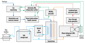
These features improve the efficiency of the liquefaction process, while maintaining the inherent simplicity of the SMR process design.1 A process schematic is provided in Fig. 1.
 |
|
FIG. 1. OSMR process flow schematic. |
The precooling load in an OSMR LNG plant is determined by the amount of waste heat recovered from the gas turbines driving the mixed refrigerant compressor. A waste gas boiler is used to consume the low-Btu fuel from the BOG recovery/N2 rejection unit and heavy hydrocarbons removed from the liquefaction plant, as well as to add control to the overall steam balance.
Refrigerants selection in LNG plants. Refrigerant selection for large baseload LNG plants is closely associated with the selection of the liquefaction technology. Propane-precooled SMR plants commonly deploy fractionation units to recover methane, ethane, propane and butane to be used in the refrigeration circuits. Cascade-style plants historically have imported propane and ethylene while using methane from the plant itself. Both these approaches of self-generating vs. importing have inherent advantages and drawbacks.
Leaner feed gas facilities, including those plants fed from lean dedicated gas fields or pipelines with heavies removed upstream, can struggle to generate sufficient refrigerants for the refrigeration circuits while also incurring a higher capital cost burden and increased operational complexity associated with the fractionation facilities. On the other hand, plants electing to import and store pure component refrigerants can see more complex logistics, refrigerant price fluctuations, greater storage needs and higher plant operating costs.
Therefore, project liquefaction technology selection should carefully consider refrigerant management strategy in the plant, including feed gas composition variations, refrigerant usage and demand, potential losses and venting on trips, availability and cost of refrigerants, and operational complexities while evaluating lifecycle costs and reliabilities. Liquefaction technology selection must take a holistic view where process efficiency, capital cost, plant physical and environmental footprint, and construction methodology all play a significant role.
Propane has been used in almost all export-scale LNG liquefaction plants as the precooling hydrocarbon refrigerant, as it is naturally available in the feed gas and has a boiling point suitable for precooling. Outside the LNG industry, propane is generally avoided as an industrial refrigerant as it is a costly (when including shipping), highly flammable and potentially explosive hydrocarbon. Ammonia has been the predominant general industrial refrigerant used since the 1800s. The benefits of ammonia as an industrial refrigerant are well known. It is a proven refrigerant with high efficiency and is used in industries from food processing to ice rinks, bobsled tracks, the Houston food bank and for cooling the international space station.2 Ammonia has been used in small-scale LNG production in a precooled mixed refrigerant process. The 200-metric-tpd Maitland LNG plant in Karratha, Western Australia uses an ammonia precooled SMR liquefaction process and has been in operation since 2007.
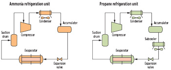
Propane vs. ammonia—a technical comparison. In properly optimized refrigeration systems, ammonia contributes to a high theoretical coefficient of performance (COP) compared to many refrigerants in use.2 A simple technical comparison of the refrigeration capabilities of ammonia and propane systems was carried out with equal refrigeration load at the same single-stage evaporation temperature. The two refrigeration circuits comprise a single-stage compressor, a condenser and a subcooler for propane, as shown in Fig. 2.
 |
|
FIG. 2. Simple refrigeration circuits for ammonia and propane. |
Several design conditions were applied:
- Ambient temperature of 25°C (77°F)
- Air cooler outlet temperature of 35°C (95°F)
- Refrigerant evaporation temperature of –25°C (–13°F)
- Refrigeration load of 37 MW.
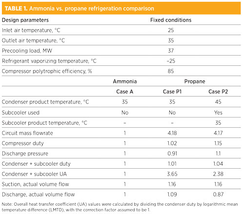 |
Table 1 provides a comparison of the propane and ammonia circuits. The ammonia circuit performance is shown as Case A, with identical propane circuit results shown in Case P1. Results for a modified propane circuit are shown as Case P2. A summary of results and observations includes:
- A like-for-like comparison of the circuits shows that a propane condenser of more than 3.6 times the size would be required due to the larger UA, assuming similar heat transfer coefficients. A propane condenser of this size can be problematic in LNG plant layouts. It should be noted that ammonia has a superior heat transfer coefficient in condensing and evaporating service compared to propane, due to its thermophysical properties. This leads to smaller equipment.
- Propane has a lower heat of compression, resulting in a lower discharge temperature compared to ammonia, which results in a lower LMTD in the condenser. The lower heat of compression of propane helps reduce the compressor load, partially offsetting a nearly fourfold mass flow compared to ammonia.
- As a second step to reduce the excessive size of the propane condenser, the propane circuit was modified by increasing the compressor discharge pressure and, therefore, the condensing temperature. This results in a larger LMTD in the propane condenser and the reduction of the condenser size. A propane subcooler was then added to the propane circuit to achieve a comparable refrigerant temperature of 35°C (95°F), as shown in Case P2.
- The use of a propane subcooler adds new equipment to the propane circuit but reduces the overall size of the propane coolers to only 2.3 times the size of the ammonia condensers, as shown in Case P2.
- The modified propane circuit in Case P2 results in an increase in propane compressor load by 15% compared to the ammonia compressor.
- The larger suction-side propane volumetric flows will lead to larger piping and heat exchanger equipment in the propane circuit compared to ammonia. With lower swept volume, the ammonia compressor would be smaller than the propane compressor.
- The use of a subcooler is critical for the efficient design of a propane circuit, while the ammonia refrigerant circuit does not require a subcooler.
- A similar pattern of results was observed when additional evaporation and compression stages were used, indicating that an ammonia refrigeration system would be smaller, more cost-effective and more efficient compared to a propane system.
- The refrigerant inventory in an ammonia circuit will be considerably smaller compared to a propane system, with smaller equipment in an ammonia precooled LNG plant compared to a propane precooled LNG plant.
- With a smaller system refrigerant inventory compared to propane, refrigerant losses and the required refrigerant makeup rates will also be smaller in an ammonia system.
- The requirement for additional bulk storage of refrigerants can be avoided in a facility with an ammonia refrigeration unit, as opposed to a propane unit. This further reduces the capital cost of an LNG plant.
- Ammonia is a readily available refrigerant with a significantly lower unit cost compared to imported refrigerant-grade propane for an LNG plant that has no fractionation unit to produce its own, therefore providing operating cost savings.
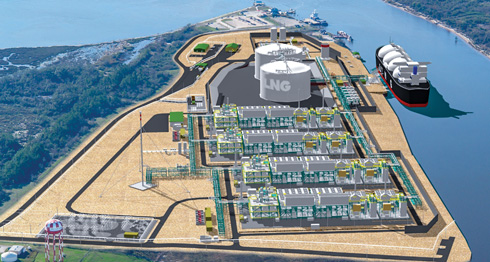
The use of ammonia for precooling in OSMR LNG trains leads to a smaller LNG train footprint and provides significant benefits toward modularization, construction, hookup and commissioning of the LNG trains. This is evident in the Magnolia LNG project, where a 115-acre site is effectively used for the 8-MMtpy (or greater) project capacity, as shown in Fig. 3.3 The smaller overall site footprint enables an ammonia-precooling-based OSMR LNG plant to further minimize environmental impacts.
 |
|
FIG. 3. Proposed train layout for Magnolia LNG. |
Safety and environmental aspects of ammonia and propane. Ammonia is widely used as an industrial refrigerant and in the fertilizer industry, and has an excellent safety record.2 The toxicity of ammonia must be carefully managed (propane is a simple asphyxiant), but as a refrigerant, ammonia provides several inherent safety advantages over commonly used propane:
- Propane is highly flammable. Ammonia will burn when encouraged, but is effectively non-flammable in most situations.
- Propane can be highly explosive in free air, and propane liquid spills under equipment can result in catastrophic boiling liquid expanding vapor explosions (BLEVEs). Ammonia is effectively non-explosive in free air and does not contribute to BLEVEs.
- Propane is heavier than air and tends to accumulate in low areas, limiting dispersion following a release. Ammonia is lighter than air and tends to disperse more readily.
- Propane releases cannot be mitigated. Ammonia releases are readily detectable and can be mitigated and controlled with simple water sprays.
- Ammonia has zero global warming potential (GWP), while propane has a GWP 3.3 times that of carbon dioxide (CO2). Both refrigerants have a zero ozone depletion potential (ODP).
Ammonia is generally stored as a liquefied gas under pressure. It is a colorless gas, but produces a pungent odor even at small concentrations, making it easier to detect during a leak. Ammonia is non-corrosive in a water-free environment, but very corrosive in the presence of moisture. Ammonia is available in various grades, and anhydrous ammonia is used as the refrigerant in OSMR plants. When released to atmosphere, ammonia will form a dense, visible white cloud as it rapidly absorbs moisture from air.
The ammonia refrigeration unit in the OSMR LNG plant is designed based on best practices in the ammonia refrigeration industry and guidance from the International Institute of Ammonia Refrigeration (IIAR). Ammonia is not vented from the plant during routine shutdowns, unlike propane in precooled SMR plants with industrial turbine drivers. Furthermore, with smaller flammable hydrocarbon inventories in the plant, an OSMR LNG plant has smaller fatality risk contours compared to a propane-precooled LNG plant, thereby leading to lower project catastrophic loss risk.
The storage and handling of ammonia is regulated in various parts of the world as a hazardous chemical. All refrigeration systems require risk assessment, and ammonia systems are not exceptions. In the US, the Occupational Safety and Health Administration’s (OSHA’s) Process Safety Management (PSM) rule 29 CFR 1910.119 provides guidelines for a comprehensive program for facilities to ensure that proper safety, maintenance and operating procedures are followed, minimizing potential hazards.2 Facilities covered by OSHA’s PSM rule are also covered by the Environmental Protection Agency’s (EPA’s) Risk Management Program (RMP), which is structured to prevent, detect and respond to accidental releases of hazardous chemicals and to inform local communities of the risks. With an appropriate application of PSM and RMP programs to ammonia refrigeration systems, safety to individuals, communities and the environment is established.
The US Federal Energy Regulatory Commission (FERC), in association with other state and federal regulatory agencies, conducted a thorough review of the ammonia-precooled OSMR-based Magnolia LNG plant design prior to approving the design to proceed for construction in November 2015. The final environmental impact statement (EIS) issued by the FERC confirmed the OSMR process to be 30% more efficient compared to a typical precooled LNG process. It acknowledged the use of ammonia as an efficient refrigerant and expressed confidence that it will be managed under OSHA’s PSM, covered by EPA’s RMP.4
Takeaway. The selection of refrigeration technology and the use of an effective precooling refrigerant can provide significant project cost savings and efficiency improvements. The historic use of propane as a precooling refrigerant is based on operational convenience rather than on process efficiency or lifecycle costs.
Ammonia is a well-proven natural refrigerant used in various industries around the world. The use of ammonia as a precooling refrigerant in LNG liquefaction plants can enable the SMR process to become more efficient, as well as reduce equipment cost. The use of ammonia in place of propane as a precooling refrigerant results in a smaller precooling refrigerant unit and a smaller LNG train footprint, leading to an overall reduction of project costs. The improved efficiency also results in a reduced emissions profile.
Although the toxicity of ammonia must be effectively managed, ammonia-precooled LNG plants result in smaller refrigerant storage volumes and a reduced volume of highly flammable refrigerants, ensuring safer plants with more compact footprints. GP
Literature cited
- Baguley J. and L. Clark, “Embracing diversity in LNG liquefaction technology—Innovation in a changing world,” LNG18, April 2016.
- American Society of Heating, Refrigerating and Air-Conditioning Engineers (ASHRAE), “Ammonia as a Refrigerant,” February 2017, online: https://www.ashrae.org//File%20Library/About/Position%20Documents/Ammonia-as-a-Refrigerant-PD-2017.pdf
- Hernandez, R., “Site selection matters,” LNG Industry Magazine, November 2017.
- US Federal Energy Regulatory Committee, “Magnolia LNG final environmental impact assessment statement,” November 2015, online: https://www.energy.gov/sites/prod/files/2015/11/f27/EIS-0498_Magnolia_LNG_FEIS_%28Nov_2015%29.pdf
 |
Nimalan Gnanendran is the Technology Manager at LNG Ltd., and has worked extensively in developing the OSMR LNG process. He has been closely involved with Magnolia LNG development work, and earlier with the Gladstone LNG project as Process Lead, working with EPC contractors during their respective FEEDs. Previously, he worked at Cool Energy, a Shell Technology Venture company, and as a Senior Research Fellow at Woodside Research Foundation at Curtin University in Perth, Australia, where he also obtained his PhD in the area of gas hydrates. He has worked on developing novel technologies for the natural gas processing and LNG industry for the past 18 yr, with a unique background in process engineering and applied research. Dr. Gnanendran has co-authored three patents and several technical publications.
 |
John G. Baguley serves as Chief Operating Officer for LNG Ltd., including Magnolia LNG, Bear Head LNG and OSMR technology. His involvement in international LNG project development and delivery spans more than 38 yr and includes project management, engineering, construction and commissioning roles. He holds a BS degree in chemical engineering from Michigan State University in East Lansing, Michigan, and is a registered Professional Engineer in Texas.


Comments