
Gas pretreatment considerations for LNG plants feeding with pipeline-quality gas
S. Mokhatab, Gas Processing Consultant, Halifax, Nova Scotia, Canada; S. Northrop, ExxonMobil Upstream Research Co., Houston, Texas; and R. Palla and B. Sharma, Honeywell UOP, Des Plaines, Illinois
LNG projects using pipeline-quality gas as feed have become more prevalent in recent years as they reduce plant equipment count, space requirements and cost. However, this pipeline gas will still require some pretreatment to remove potentially freezable components ahead of the liquefaction process. The gas pretreatment system must be robust and flexible to handle a wide range of feed compositions, since the gas transmission pipeline may be fed by many different (and possibly intermittent) sources.
Also, the gas may pass through multiple compressor stations, potentially affecting gas quality through condensation of heavy hydrocarbons, for example. As such, great interest exists in developing robust, reliable and cost-efficient natural gas pretreatment solutions that reduce a meaningful portion of the capital and operating costs of pretreatment. This article discusses the most appropriate technologies and process configurations for tackling common contaminant issues in pipeline-quality gas feeding LNG plants.
Introduction. While each facet of the LNG production plant is important, the gas pretreatment section of the plant plays a critical role in treating the gas to meet its final sulfur specifications, and to meet the other purity levels required by the natural gas liquefaction unit. The specifications to be met are hydrogen sulfide (H2S) removal to under 4 ppmv (usually already met by pipeline spec), carbon dioxide (CO2) to < 50 ppmv, total sulfur under 30 ppmv, water (H2O) to less than 0.1 ppmv, and mercury (Hg) to 0.01 μg/Nm3. Heavier hydrocarbons such as C5+—and specifically benzene—are of concern for liquefaction units due to their relatively high freezing points. Consequently, C5+ must be removed to less than 0.1 mol% and benzene to < 1 ppmv.
The required pretreatment steps depend strongly on the level of feed gas components. In fact, whether the gas comes from a pipeline grid or from a dedicated field makes a difference to the design and operation of the gas pretreatment units. For example, the low levels of sulfur compounds in pipeline-quality feed gas to an LNG plant mean that only CO2 removal is required in the acid gas removal unit.
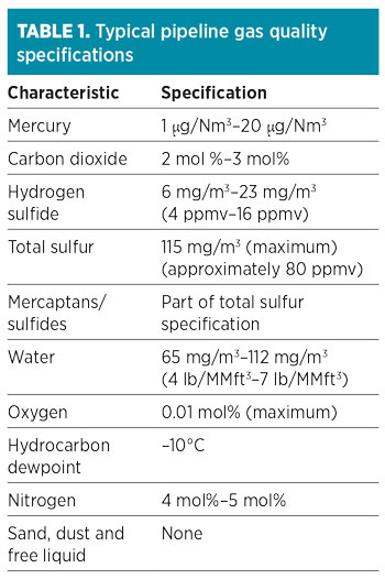
Typical pipeline gas quality specifications are shown in Table 1. Most pipeline gas contracts have allowable limits for specified contaminants, which can be higher than what is found in the pipeline gas. However, the level of these contaminants may vary substantially within those limits over time.1 Therefore, it is essential to know the gas sources feeding the pipeline to the LNG plant to understand the potential range of contaminants and to establish a proper design basis that will aid in selecting the most appropriate technology and process configuration for the gas pretreatment section.
 |
Mercury removal. Although little mercury is expected in pipeline-quality gas, mercury removal is required to avoid the potential risks of mercury corrosive attack on the aluminum heat exchangers in the downstream cryogenic section of an LNG plant. Alloys of aluminum are prone to liquid metal embrittlement, causing serious structural damage, particularly when liquid mercury comes into contact with air or water.
Two types of non-regenerative mercury removal options are available—sulfur-impregnated activated carbon systems and metal sulfide beds. The common and traditional approach to mercury removal has historically been through the use of sulfur-impregnated activated carbon beds. Existing sulfur-impregnated activated carbon options tend to be less effective at positions upstream of molecular sieve (MS) drying systems or glycol injection due to the risk of capillary condensation in the micropores of the carbon substructure. Where mercury removal unit (MRU) locations have been in the “up-front” position, they are exposed to raw gas that is often at or close to its dewpoint and contains entrained liquids. In such scenarios of wet gas exposure, sulfur-impregnated activated carbon is prone to sulfur dissolution and micropore blocking, which may contribute to shortened service life.
One approach to solve this issue is to use nonregenerative metal sulfides to remove mercury from the raw gas upstream of the dryers and the amine unit. Using larger vessels, this approach also protects the brazed aluminum heat exchanger and ensures less mercury contamination in and around the process plant. These high-capacity mercury adsorbents, which are typically engineered using a copper-based active component finely dispersed across an alumina substrate, can result in longer lifespan, reducing the lifecycle cost of mercury removal. Mercury guard bed (GB) adsorbents can be supplied in their oxidized form or sulfided form, offering flexibility. The oxidized form can be pre-sulfided or sulfided in-situ, if H2S is present in the feed gas.
The protection of aluminum heat exchangers can also be accomplished, using a layer of silver-containing molecular sieve inside the dehydration vessels. The active silver forms an amalgam with any mercury present, and the zeolitic substrate adsorbs moisture in the gas to be treated. This approach offers flexibility in being regenerable, as the mercury-containing gas is bypassed around any cryogenic equipment. If necessary, the mercury-containing regeneration gas can be treated with a small, non-regenerative GB.
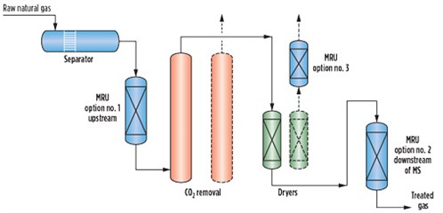
Fig. 1 shows the possible options to remove mercury in an LNG plant. Lifecycle costs, adsorbent disposal methods, mercury levels, environmental limits, operating hazards and plant operator procedures must be evaluated in the selection of a suitable mercury removal system. The optimum mercury removal method can also be a combination of non-regenerative and regenerative mercury removal systems. As the feed gas is pipeline-quality with limited contaminants, the recommendation for the location of the unit is upstream of the CO2 removal unit.
 |
|
FIG. 1. Possible options for mercury removal from feed gas. |
CO2 removal. A number of technologies are used commercially to remove CO2 from natural gas, as outlined in the following sections.
Chemical solvents. These solvents chemically absorb H2S, CO2 and, to some extent, carbonyl sulfide (COS). Organic sulfur components do not chemically react with the solvent, though some physical absorption may take place. Chemical processes that use amine solvents (most often promoted methyl diethanolamine) are especially suitable when contaminants at relatively low partial pressure must be removed to very low concentrations, making this a preferred option for CO2 removal from pipeline-quality feed gas to an LNG plant.
Physical solvents. These solvents can remove acid gases and organic sulfur based on physical absorption. Compared to chemical solvents, physical solvents absorb more hydrocarbons, and consequently have higher hydrocarbon losses. Physical solvents are generally economical when the partial pressure of acid gases (CO2 and H2S) in the feed gas is high (e.g., > 100 psi), the treated gas specification is moderate and a large feed gas volume will be treated. For LNG plants being fed with pipeline-quality gas, the partial pressure of the CO2 is relatively low in the feed gas, so a physical solvent is likely not the ideal option.
Hybrid solvents. These solvents, which take advantage of the benefits of chemical and physical solvents, are particularly useful for applications where significant organic sulfur compounds (i.e., mercaptans) and COS are present in the natural gas. Since these components are not expected to be present in significant concentrations in the pipeline-quality feed gas to an LNG plant, a hybrid solvent is not generally considered to be a good option.
Molecular sieves. Molecular sieves of certain pore sizes (typically 4A/5A or 13X) trap the CO2 and H2S within the pores. CO2 and H2S are recovered in a regeneration step, using a slipstream of hot treated (product) gas.
If the pipeline gas contains little CO2 (e.g., < 1 vol%–2 vol%), then a molecular sieve unit (MSU) may be used to remove residual contaminants. While molecular sieves can remove low percentages of CO2 (< 2 mol%) to meet a 50-ppmv LNG specification, the disposal of spent regeneration gas becomes a challenge. Since LNG peakshaver plants can typically recycle regeneration gas to the source pipeline, CO2 removal using an MSU is popular in such applications.
The amount of regeneration gas required is a function of the feed gas CO2 level, and it is typically > 10% of the feed gas flowrate. If the spent regeneration gas can be used as fuel or sent elsewhere, this can be an alternative for LNG pretreatment for smaller-scale LNG plants. If not, then regeneration gas treatment is needed for the spent regeneration gas (which may be high in CO2, H2S and/or mercaptans). This means an additional unit (solvent/membrane system) for the regeneration gas is needed to remove the concentrated contaminants. This adds capital and operating costs and complexity to the standalone MSU.
Since large-size plants will have a significant volume of spent regeneration gas to dispose/treat, a molecular sieve for CO2 removal is not the most suitable option for large-scale LNG units or feed gas containing more than 2 mol% CO2. Newer developments have been seen in this field with the use of temperature swing adsorption (TSA) and temperature-pressure swing adsorption (TPSA). The molecular sieve approach may be considered for pretreatment of small- to mid-scale (< 1.5 MMtpy) LNG projects.
MSUs can also be designed to remove trace amounts of methanol in addition to water. If methanol is present to suppress upstream hydrate formation, then additional design capacity will be required, and the size of the unit will be impacted. In these cases, molecular sieves will be exposed to trace amounts of amine, glycol or methanol in the form of aerosol. Moreover, water-saturated and high-pressure regeneration gas may cause refluxing and hydrothermal stress. Proper unit design and robust material with a strong binder is essential for longer molecular sieve life.2
Membranes. Membrane systems operate on the principle of selective permeation via solubility and diffusivity of certain gas molecules when exposed to membrane material. Each component has a specific permeation rate, where the components with higher permeation rates (such as water, CO2 and H2S) will permeate faster through the membrane film than components with lower permeation rates (such as nitrogen, methane, ethane and heavier hydrocarbons). The dissolved gases in the membrane materials move across the membrane barrier under a partial pressure gradient, which is established by maintaining a high feed pressure on one side of the membrane while maintaining a low pressure on the permeate side.
Membranes are well suited for bulk removal of CO2 at high inlet partial pressure. Depending on the feed CO2 content, a treated gas specification of 1 mol%–2 mol% CO2 can be economically achievable with membranes. However, membrane technology cannot meet the 50-ppmv CO2 specification required by LNG facilities. As the feed gas passes across the membranes, its CO2 content decreases. As a result, the partial pressure of CO2 decreases as the gas moves along the membrane unit. As the partial pressure of CO2 decreases, the differential partial pressure of the component to be removed (CO2, in this case) also decreases. Therefore, deeper removal of CO2 requires a much larger membrane surface area. As the feed CO2 level goes down, relatively higher levels of hydrocarbon permeation occur. This loss of hydrocarbons can be reduced by recovery in a recycle loop (i.e., a two-stage system), but it requires compression that increases the operational complexity.
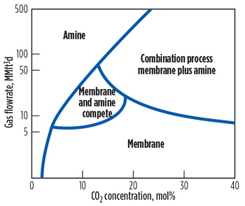
The economic advantage of using membranes for CO2 removal applications is enhanced for inlet gas streams containing above approximately 15 mol% CO2. In such cases, an economical method to achieve final specifications is to combine membranes with a solvent-based (amine) acid gas removal process. Fig. 2 compares the range of applicability of amines, membranes and combination (membrane plus amine) treating processes. It shows that for pipeline-quality gas with low CO2 concentration and relatively high flowrates, amine absorption is preferable to membranes.
 |
|
FIG. 2. Comparison of membrane and amine processes for CO2 removal.3 |
Technology selection. Facing the vast range of applicable technologies, the process designer’s challenge lies in selecting the optimal CO2 removal technology for the project at issue. As described above, the most suitable processes for CO2 removal from pipeline-quality feed gas are chemical solvents and molecular sieves (molecular sieve only if initial CO2 level is low enough).
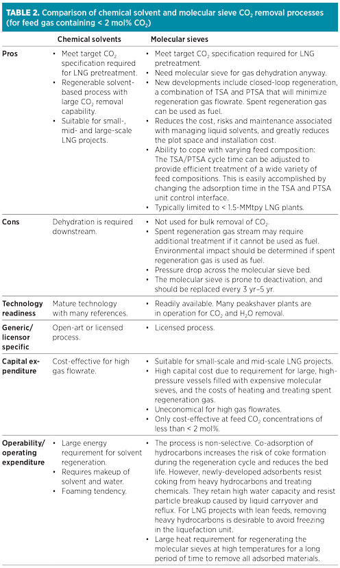
Table 2 gives a summary of the comparison of chemical solvent and molecular sieve CO2 removal processes. The main advantage of molecular sieve systems (if CO2 inlet concentration is low enough) is that molecular sieve dehydration is required anyway, so CO2 removal would require only some additional bed volume and regeneration gas. However, molecular sieves are not used for bulk removal of CO2, and this process is not favored over typical solvent-based processes due to a lack of robustness (adaptability to variation in feed gas concentration). Furthermore, another spent regeneration gas treatment unit is required if the molecular sieve unit is being used for more than dehydration.
 |
While some liquid solvent dehydration technologies can also achieve the necessary water specification, they have less flexibility in operating range and are less robust than the MSU design.
Water and mercaptans removal. Dehydration of the feed gas to meet the target water specification is required to avoid freezing/solidification in the cryogenic section of the LNG plant. The preferred method of water removal is bypassing the wet gas through fixed beds of molecular sieves. Molecular sieve type 4A is more stable and has higher water uptake capacity than a 3A sieve. Since 4A can withstand higher regeneration temperatures up to 280°C (536°F), regeneration gas requirements are lower compared to a 3A sieve. This is favorable, since regeneration gas is recycled back to the inlet of the amine unit.
MSU can also remove some of the sulfur compounds, such as mercaptans, to meet the target specifications for LNG product. While moisture removal is traditionally done with smaller-pore-size 3A and 4A molecular sieves, mercaptans/sulfur removal is done with larger-pored 5A and 13X types. A 5A type molecular sieve is used for trace removal of H2S and the removal of light mercaptans, while a 13X molecular sieve is used for adsorption of heavy/branched mercaptans. However, co-adsorption of benzene, toluene, ethylbenzene and xylene components (with concentrations higher than 30 ppmv) on 13X molecular sieves will result in an increase in the length of the molecular sieve bed. These components can also cause separation problems in the physical absorption process used to recover the mercaptan species from the spent regeneration gas. The practical solution is to use a 5A molecular sieve for removing light mercaptans in the gas phase and removing the heavier mercaptans with the LPG and C5+ cuts.
Oxygen mitigation measures. High oxygen (O2) concentrations in US pipeline natural gas (greater than 10 ppmv) can potentially impact the molecular sieve dehydration system design, especially in the presence of any trace sulfur. The presence of O2 in the regeneration gas results in water formation due to oxidation of the hydrocarbons during the regeneration heating cycle. Using molecular sieves to dehydrate natural gas containing sulfur and O2 requires special consideration. When O2 is present in the regeneration gas stream in high amounts, the presence of H2S and organic sulfur due to slip through the upstream amine unit can impact the dryer design. During the regeneration heating cycle, the sulfur species and O2 found in the regeneration stream can react to form elemental sulfur and water. Wet elemental sulfur may be very corrosive to the carbon steel in the cooler parts of the regeneration section.
The use of 3A adsorbent and low-temperature regeneration is not recommended to mitigate the effects of O2 and sulfur in dehydration applications, as this can lead to short bed life and poor unit performance. This is particularly true for LNG service where onstream time is critical to maximize LNG production.
 |
|
FIG. 3. Closed loop regeneration for O2-bearing gas.1 |
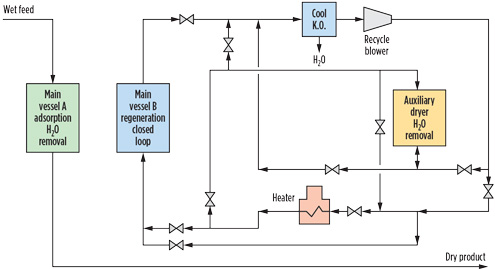
Appropriate design with a closed loop regeneration system can be used to mitigate water and sulfur formation by using a regeneration gas loop independent of the dry product gas (Fig. 3). During the heating cycle, any O2 from makeup feed gas to the closed regeneration gas loop is reacted to extinction so that no O2 remains by the end of the heating cycle.1,4
Heavy hydrocarbon removal. Pipeline gas is usually considered lean with respect to ethane, propane and butane, as these components are normally recovered to make higher-value natural gas liquids (NGL) while reducing the Btu value of the gas to acceptable levels. The levels of C5+ hydrocarbons may become elevated if an upstream NGL recovery plant goes offline, or if certain lean gas wells do not flow through an NGL recovery plant. Since NGL have already been extracted from pipeline gas in most cases, the primary purpose of removing heavy hydrocarbons upstream of an LNG facility is to prevent freezing in the downstream liquefaction section that could result in blockages and reduced capacity.
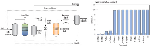
Cryogenic technology is not the most cost-effective method to remove small quantities of C5+ hydrocarbons due to the high capital and operating costs associated with expanders, columns and compressors. Additional process challenges may arise if liquids are not sufficient to provide scrub column reflux during startup, and it may be necessary to purchase NGL to make the process work. For lean gases where the primary purpose is removal of trace heavy hydrocarbons and not NGL production, adsorption technology can offer a significant advantage. The primary reason for this is that an adsorbent-based system operates at high pressure with a low pressure drop, and does not require an expander and compressor commonly found in an NGL extraction unit. The adsorption system also has the advantage of removing heavy components without removing lighter hydrocarbons (Fig. 4). Therefore, the LNG heating value is comparable to that of the pipeline feed gas.
 |
|
FIG. 4. Example of a TSA-based hydrocarbon removal process.a |
The primary differences between a molecular sieve dehydration unit and an adsorbent-based hydrocarbon removal unit are that hydrocarbon removal units generally have a shorter adsorption time of 2 hr–3 hr, use series cooling and heating regeneration, require the use of internal insulation for the adsorbers to minimize regeneration heat requirements, and require the use of different adsorbents. However, these flow schemes do have a successful history, as they are similar to CO2 removal in peakshaver units (which run on fast cycles), and may also use internal insulation to minimize the quantity of regeneration gas.
Takeaway. The selection of the most appropriate gas pretreatment strategies for LNG plants being fed with pipeline-quality gas is case-specific. The most relevant parameters to be considered in the selection will depend on the particular conditions of the LNG project.
Specifically, a full range of feed compositions with all potential contaminants, required capacity of the plant, as well as project investment criteria, can greatly affect this decision. GP
Literature cited
- McIlroy, C., A. Hatami, R. Palla and F. Nowak, “Successful mitigation of oxygen and higher hydrocarbon presence in treating pipeline natural gas for North American LNG projects,” 94th Annual GPA Convention, San Antonio, Texas, April 12–15, 2015.
- Rastelli, H. and J. S. Shadden, “Use of modeling to optimize severe duty natural gas dehydrators,” 88th Annual GPA Convention, San Antonio, Texas, March 8–11, 2009.
- Scholes, C. A., G. W. Stevens and S. E. Kentish, “Membrane gas separation applications in natural gas processing,” Fuel, Vol. 96, Iss. 1, 2012.
- Yong, J., T. Maramba, C. McIlroy and B. De Jonckheere, “Design considerations for gas pretreatment at an LNG liquefaction facility,” Gastech, Barcelona, Spain, Sept. 17–20, 2018.
Note
aHoneywell UOP’s SeparSIV system
 |
Saeid Mokhatab is a world-class expert in the natural gas processing industry who has been actively involved in different aspects of several large-scale gas processing projects, from conceptual design through plant startup and operations support. He has presented on gas processing technologies worldwide and has published 300 technical papers and two renowned Elsevier handbooks, which are considered by many as major references to be used for any gas processing/LNG project in development. As a result of his work in the natural gas industry, he has received a number of international awards and medals, and his biography has been listed in prestigious directories.
 |
Scott Northrop is a Gas Treating Advisor in the production technologies function of ExxonMobil’s Upstream Research Co. in Houston, Texas. He has 30 yr of experience in the industry, and is the author/coauthor of a number of patents, presentations and articles on a variety of related subjects. He sits on Technical Section F of the Gas Processors Association (GPA), and has served on the board of directors of Alberta Sulfur Research Ltd. in Canada. Dr. Northrop received his BS degree from Washington University in St. Louis, Missouri, and an MS degree and PhD from the California Institute of Technology, all in chemical engineering.
 |
Raj Palla is a Senior Business Development Manager for Honeywell UOP’s gas processing division. He has worked with UOP since 2006 in business development and technical sales support activities for various gas processing technologies. Previously, he worked at the Gas Technology Institute in the US for 15 yr. Mr. Palla has directed research projects in sub-quality gas upgrading, treating, dehydration, gas-liquid membranes and H2S scavenging. He has more than 26 yr of experience in the industry, is the author/coauthor of a number of presentations and articles on a variety of related subjects, and holds seven US patents. He holds an MS degree in mechanical engineering from the Illinois Institute of Technology.
 |
Bhargav Sharma is an Account Manager at Honeywell UOP with more than 17 yr of natural gas industry experience. He holds a number of patents in the gas treating area and has co-authored several technical papers. Over the past 12 yr, Mr. Bhargav has worked in engineering, research and development, and technical sales associated with a range of UOP gas purification and adsorption technologies. Prior to UOP, he worked at the Gas Technology Institute’s Gas Processing Research and Development Center for 5 yr in various roles. Mr. Bhargav obtained his MBA from the University of Houston–Victoria, an MS degree in chemical engineering from the Illinois Institute of Technology and a BS degree in chemical engineering from the L. D. College of Engineering in India.


Comments