
Achieve higher operational efficiency with amine system improvements
D. K. Ralli and P. S. Chauhan, Oil and Natural Gas Corp. (ONGC), Mumbai, Maharashtra, India
Oil and Natural Gas Corp. (ONGC) operates a plant at India’s western coast to extract value-added products from natural gas and make crude oil suitable for refining. The plant receives approximately 11.5 MMm³d of natural gas, which is treated in gas sweetening units (GSUs) to remove acid gases. Gases from the crude stabilization unit and condensate fractionation unit are also mixed with a natural gas stream prior to gas sweetening. The sweet gas is processed in cryogenic LPG and ethane/propane recovery units (EPRUs), producing LPG, low-aromatic naphtha (LAN), and an ethane-propane mixture as value-added products. The plant has three GSUs, two of which (GSU-12 and GSU-13) were commissioned in 1990, and a third (GSU-14) which was commissioned in January 2014.
An amine-based sulfinol process has been used in the plant for gas sweetening. The sulfinol process is a regenerative process that is widely used to reduce the concentration of hydrogen sulfide (H2S), carbon dioxide (CO2), carbonyl sulfide (COS) and mercaptans in gases to low ppm levels. This process uses a mixture of solvents, which allows it to behave as both a chemical process and a physical absorption process.
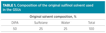 |
Until 2005, a proprietary sulfinol solventa comprising sulfolane, a physical solvent, di-isopropanolamine (DIPA), a chemical solvent and water (Table 1) was used for the removal of both H2S and CO2 to less than 4 ppm and 50 ppm, respectively. This adequately met the specifications required in the downstream cryogenic units.
The system operated efficiently and without trouble until April 2005, when severe foaming problems were encountered in the GSUs.
Foaming and associated problems. Foaming is detected by physical inclusion of gas bubbles enveloped by the amine solution. This happens primarily due to contamination of the solution with surface-active agents—materials that reduce surface tension, including liquid hydrocarbons.
Surface tension is also affected by operating conditions; higher temperature and pressure tend to reduce surface tension. Temperature has the upper hand in impacting surface tension of an aqueous amine solution. Higher pressure, to a lesser extent, affects solution-foaming tendency. At higher pressures, the solubility of liquid hydrocarbons in the amine solution increases, thereby changing the surface structure of the aqueous solution and rendering a lower surface tension. This increases the tendency of the system to foam.1
Foaming symptoms. An amine system subjected to foaming exhibits the following behaviors:
- Sudden increase in the column’s differential pressure is the first alarming sign of a foaming system. When the contactor faces foaming and as the foam height increases, the void volume inside the column is reduced, which leads to higher pressure drop.
- Amine carryover to downstream equipment is a late warning of foaming in the column and is indicated by erratic or abnormal levels in the downstream knockout drums.
- Loss or reduction in the rich amine flowrate is accompanied by an erratic or abnormal level indication in the absorber column’s bottom section.
Foam inducers. Clean, uncontaminated amine does not form stable foam. Amine system foaming results from contaminants introduced to the system through the feed gas, makeup water or recycled streams, or is generated in the system, such as degradation and corrosion products. Several common causes of foaming are identified:2–5
- •Liquid hydrocarbon introduced by sour feed gas is the primary cause of foaming problems in gas sweetening plants. Liquids can be introduced as mist entrainment or carryover, or they can be formed inside the column if the lean amine entering the column is cooler than the sour gas dewpoint. The impact of liquid hydrocarbon comes from its solubility in the aqueous amine solution, which reduces its surface tension. Secondary and tertiary amines, more than primary amines, tend to foam in the presence of liquid hydrocarbons due to the higher solubility of liquid hydrocarbon in secondary and tertiary amines.
- Solid particulate contamination, especially iron sulfide (FeS), is one of the major causes of foaming. Iron sulfides, as very fine particulates, are difficult to remove by conventional mechanical filters, tend to concentrate at the liquid-gas interface and increase foaming stability. FeS, a byproduct of corrosion activities of H2S and carbon steel piping, could be carried over from the sour feed gas or generated in the amine solution due to high solution acid gas loading, high velocities and formation of acidic degradation products.
- Water-soluble surfactants, such as corrosion inhibitors, well treating compounds and excessive antifoam agent tend to dissolve in aqueous solutions and reduce surface tension, thereby leading to foaming.
- Amine degradation products lead to changes in the amine solution’s structure and may increase the foaming tendency. Degradation products are formed either by direct reaction of the amine and constituents in the feed gas or by thermal decomposition of the amine.
Impact of foaming and control measure. Foaming in the amine system leads to high capital losses due to several reasons:
- Temporary loss of sour gas processing capability
- Reduction in sales and fuel gas production
- Carryover of solution in downstream units and solvent loss.
In view of this scenario, the process licensor in 2005 recommended top-up with an accelerated amine mixture in place of DIPA, therefore switching slowly from the original sulfinol solvent to a higher-tech sulfinol solventb (Table 2). The key constituent in this higher-tech solvent, aMDEA (a mix of piperazine in MDEA), was easily available in the local market for quick top-up. It was suggested that the switchover process could be carried out gradually, by top-up with aMDEA after exhausting the remaining DIPA inventory, or under a procurement process.
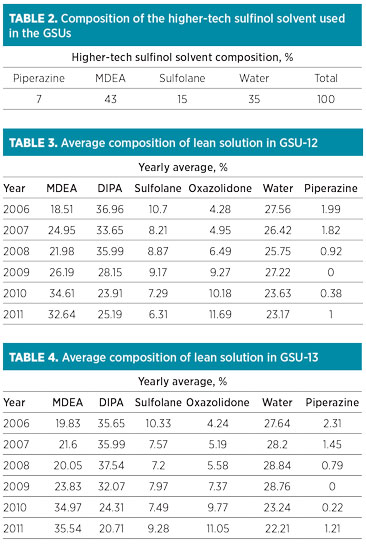 |
Changes in amine system. After exhausting the DIPA inventory, further solution top-up was carried out with sulfolane, MDEA and piperazine only. The changes in composition of solution in GSU-12 and GSU-13 from 2006–2011 are shown in Table 3 and Table 4, respectively.
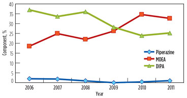
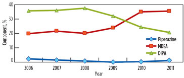
Over the years, the DIPA content in the solution was reduced from 40% to approximately 25% and 21% in GSU-12 and GSU-13, respectively. MDEA content increased from 0% to 33% and 35% in GSU-12 and GSU-13, respectively. Trends of DIPA, MDEA and piperazine in GSU-12 and GSU-13 from 2006–2011 are presented in Fig. 1 and Fig. 2, respectively.
 |
|
FIG. 1. Trend of DIPA, MDEA and piperazine in lean solution in GSU-12. |
 |
|
FIG. 2. Trend of DIPA, MDEA and piperazine in lean solution in GSU-13. |
Standard analytical test methods have been used to evaluate lean solution quality and to determine the levels of CO2 and H2S in sweet gas. A proprietary evaluation method examined lean solution components, including piperazine, MDEA, DIPA, sulfolane and oxazolidone. Water content has been determined using SMS-1608, and CO2 in sweet gas has been determined using the SMS-1742 method. The level of H2S in sweet gas is estimated using detector tubes, as per method ASTM-4810.
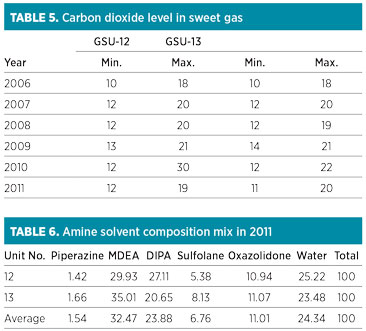
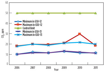
The GSU performances regarding H2S and CO2 concentration in the sweet gas remained satisfactory. The annual average range of CO2 content in sweet gas from both units was found to be within the maximum permissible limit of 50 ppm (Table 5/Fig. 3). The peak value of 30 ppm was observed in 2010 in GSU-12 only. The H2S concentration remained less than 1 ppm—well below the permissible limit of 4 ppm measured consistently in both sweet gas units over the years.
 |
 |
|
FIG. 3. CO2 in sweet gas. |
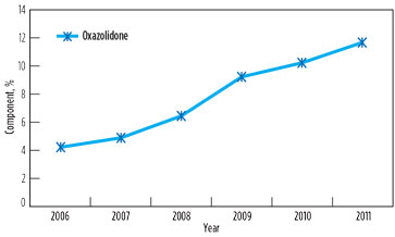
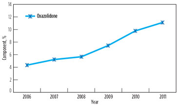
However, foaming and associated problems again manifested in 2011, affecting capacity utilization in both GSUs. The root cause of the problem was found to be the contamination of solution with surface active agents above threshold concentration, due to low solvent inventory (8%) and an increase in degradation product oxazolidone beyond the maximum prescribed limit of 10%. Changes in oxazolidone content in lean solutions in GSU-12 and GSU-13 from 2006–2011 are presented in Fig. 4 and Fig. 5, respectively.
 |
|
FIG. 4. Change in oxazolidone content in lean solution in GSU-12, 2006–2011. |
 |
|
FIG. 5. Change in oxazolidone content in lean solution in GSU-13, 2006–2011. |
It is significant to note that, in 2006, the oxazolidone levels in both GSUs under operation since 1990 were only 3%–4%. However, a drastic rise was observed when the addition of DIPA was stopped. It is supported by the fact that, due to the availability of piperazine to react quickly with CO2, DIPA could have an ample opportunity to undergo a side reaction of producing oxazolidone.
Apart from oxazolidone, the presence of liquid hydrocarbons or other contaminants in sour gas will certainly have more impact on foaming if levels of amine solvent are low, due to the higher concentration of contaminants. Therefore, it was decided to raise the solvent inventory in the absorber column to 25%. The composition of the comingled mixture of the amine solvent was not proportionate (Table 6).
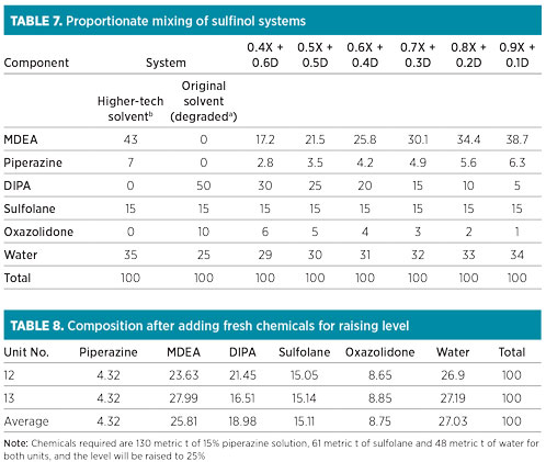 |
The solvent concentration of MDEA, piperazine, sulfolane and water (on a DIPA- and oxazolidone-free basis) did not conform to the recommended proportion of 43:7:15:35 for the higher-tech solvent in both the units. Theoretical calculations of the compositions corresponding to various comingled sulfinol solvent fractions are listed in Table 7.
The composition mix in both units was close to 0.6X + 0.4D, which could be achievable with minimum use of chemicals. However, the authors needed to achieve the higher-tech solventb composition. Two options were considered to meet this goal, as explained in the following sections.
Comingled solvent in both units. It was necessary to raise the operating level of the comingled solvent in the solution tanks from 8% to 25%. The average expected composition that could be achieved in both GSUs after increasing the level to 25% by adding fresh chemicals is presented in Table 8. Note: Required chemicals include 130 metric t of 15% piperazine solution, 61 metric t of sulfolane and 48 metric t of water for both units, and the level will be raised to 25%.
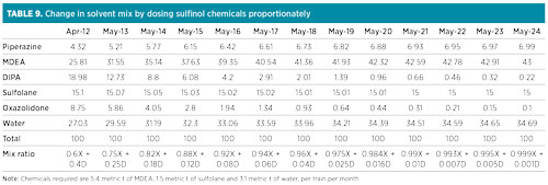
After achieving this 25% level, considering a top-up of 10 metric t of fresh solvent per unit per month, and projecting the reduction in DIPA/oxazolidone content based on the available trend, the desired higher-tech solvent composition was theoretically expected to be obtained in 2024 (excluding DIPA degradation to oxazolidone). The projected average solvent composition in the coming years, along with the approximate mix ratio with reference to Table 7, has also been computed and presented in Table 9. Required chemicals include 5.4 metric t of aMDEA, 1.5 metric t of sulfolane and 3.1 metric t of water per train per month.
 |
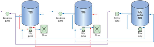
Option 2: Solvent replacement in one unit. A complete solvent switch in one unit and the continued comingling of solvent in the other were proposed. The schematic for storage and interconnections in GSU-12, GSU-13 and the buffer solution tank is presented in Fig. 6. The following steps were required to be followed:
- Transfer approximately 250 metric t of solvent from GSU-12 to GSU-13 during a planned turnaround
- Prepare fresh higher-tech solvent solution for circulation in the buffer solution tank
- Restart GSU-12 with fresh higher-tech solvent, using the buffer solution tank and its booster pump for solvent circulation in GSU-12
- Transfer the surplus quantity in GSU-13 to T1201 and use it for future top-up in GSU-13.
 |
|
FIG. 6. Schematic for solution storage and interconnections in GSU-12 and GSU-13 buffer solution tank circulation. |
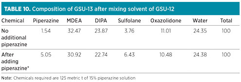
The composition of GSU-13 solution after mixing of GSU-12 solution is shown in Table 10. Fresh chemicals for attaining and maintaining the recommended proportion in GSU-13 were not required for the next 18 mos, due to available buffer stock. However, it was necessary to add piperazine to obtain its concentration proportionate to MDEA in the solvent mix. Approximately 18.75 metric t of piperazine (dry basis), equivalent to 125 metric t of 15% solution, were required for the solvent inventory in GSU-13. Water content was adjusted through the control of steam condensate addition at a 10-metric-tpd/train in both sweetening units. The expected new composition of GSU-13 after adding piperazine is also depicted in Table 10.
 |
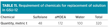
After exhausting the buffer solvent inventory, fresh chemicals would be required for GSU-13 as a maintenance dose at 5.4 metric t of aMDEA, 1.5 metric t of sulfolane and 3.1 metric t of water per month. The target composition mix will only be achieved in 2024, in line with Table 9. The chemicals required for replacing the existing solvent in GSU-12 with 320 metric t of higher-tech solvent are presented in Table 11. The maintenance dose in GSU-12 contains 5.4 metric t of aMDEA, 1.5 metric t of sulfolane and 3.1 metric t of water per month.
As piperazine is relatively volatile, frequent top-up was required. Table 1 and Table 2 show that the loss of piperazine was approximately 0.8% per train per year. Accordingly, a 15% piperazine solution was required at 17 metric tpy for each train, or 34 metric tpy to replenish the dose in the solution for both trains.
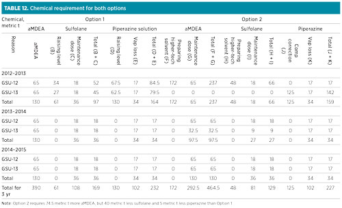
The total chemical requirements for both units for the two options are presented in Table 12, with the assumption that there has been no solvent loss due to carryover or leaks.
 |
Option 2 was preferred for the future solvent switchover strategy in the GSU, as the higher-tech solvent composition could be achieved in 2012 instead of 2024. Therefore, with the new gas sweetening unit (GSU-14) in the new process unit, there would be two units with higher-tech solvent.
 |
Considering Option 2, the complete changeover to the higher-tech solvent solution was successfully carried out during a turnaround of GSU-12 in May 2012, and the older, comingled solution of GSU-12 was mixed with GSU-13 to raise its level.
Post-changeover scenario. After the changeover to the higher-tech solvent in GSU-12, the system was studied to see if the desired objectives had been achieved.
The benefits of a complete changeover to the higher-tech solvent in one of the units showed the following results:
- No foaming, capacity restriction or solution carryover were seen in either GSU
- The higher-tech solvent has the advantage of having a higher CO2 removal rate due to piperazine, and no degradation product like oxazolidone is formed from MDEA
- A reduction of hydrocarbon level was seen in acid gas from GSU-12, as compared to GSU-13.
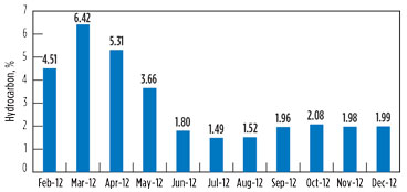
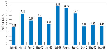
Variation in the hydrocarbon content in the vent gas is presented in Fig. 7 and Fig. 8 for GSU-12 and GSU-13, respectively.
 |
|
FIG. 7. Variation in the hydrocarbon content in vent gas for GSU-12. |
Post-changeover (i.e., July–December 2012), the average hydrocarbons percentage in vent gas from GSU-12 was 1.84%, whereas it was 6.48% for GSU-13. Considering that the average quantity of acid gases from one of the GSUs is 150,000 m3d, the quantity of hydrocarbon saved by upgrading the amine solvent is approximately 7,000 m3d per GSU, which is equivalent to INR 58,800/d. The savings from the amine solvent changeover per GSU are 215 lakh/yr, taking the gas price to INR 8,400/1,000 m3.
 |
|
FIG. 8. Variation in the hydrocarbon content in vent gas for GSU-13. |
Considering the benefits of the solvent switch in GSU-12 by a complete changeover in place of the top-up method, the solvent of GSU-13 was also switched to the higher-tech solvent chemicals by complete changeover during a turnaround in June 2014.
Takeaway. The process of solvent switch by the top-up method, which was initiated at the plant in 2005, could not control the problems of foaming and capacity restriction. However, removal of H2S and CO2 from the sour gas was not impacted by the partial solvent switch. Reasons for foaming were found to be the presence of contaminants in the solution, higher-than-recommended oxazolidone content and low solvent inventory.
Solvent switch by the top-up method triggered DIPA to produce more oxazolidone, rather than its reaction with CO2, for which piperazine was available in the comingled solution. The mode of complete changeover of GSU solvent was found to be a better option than the top-up method.
Switching from the original sulfinol solventa to the higher-tech sulfinol solventb also resulted in the use of aMDEA, a chemical readily available in the local market, over DIPA, which is an imported chemical. Therefore, inventory management became convenient and cost effective. Moreover, accumulation of byproduct oxazolidone and reclamation operations are completely avoided.
Apart from resolving the operational problems of foaming and capacity restriction and achieving the trouble-free functioning of GSUs, a reduction in emissions of hydrocarbons in acid gas was seen, with an overall savings of 215 lakh/yr per GSU, considering a gas price of INR 8,400/1,000 m3. GP
Acknowledgments
The authors claim that the views expressed in this article are their own and not those of the company they represent. They also extend their gratitude to all those who helped, supported and encouraged them during this work.
Notes
aSulfinol-D
bSulfinol-X
References
- Al Ghamdi, A. M., “Study underscores effectiveness of antifoaming agent in DGA sweetening process,” Oil & Gas Journal, May 20, 2000.
- Kohl, A. L. and R. Nielsen, Gas Purification, 5th Ed., Gulf Publishing Company, Houston, Texas, 1997.
- Pauley, C. R., “Face the facts about amine foaming,” Chemical Engineering Progress, July 1991.
- Von Phul, S. A., “Sweetening process foaming and abatement,” 51st Annual Lawrence Reid Gas Conditioning Conference, Norman, Oklahoma, February 25–28, 2001.
- Von Phul, S. A., “Sweetening process foaming and abatement Part 2: Case studies,” 52nd Annual Lawrence Reid Gas Conditioning Conference, Norman, Oklahoma, February 24–27, 2002.
 |
D. K. Ralli is Deputy General Manager with Oil and Natural Gas Corp. Ltd. in Mumbai, India. He has 33 yr of experience in quality assessment and process quality control of drilling fluids, crude oil, natural gas and value-added products. He holds an MTech degree in polymer science and technology from the Indian Institute of Technology in Delhi. He has been instrumental in developing lab facilities for gas sweetening units and effluent water, providing technical support for resolving operational problems, and implementing third-generation gas sweetening solvent systems.
 |
P. S. Chauhan has 38 yr of experience in the field of hydrocarbon processing and products quality management. He has served as Head of Refinery and Process Chemistry Stream for Oil and Natural Gas Corp. Ltd. Mr. Chauhan holds a postgraduate degree in chemistry.


Comments