
Prevent seal contamination and failure with a reliable gas supply solution
Centrifugal compressors are used in processes for producing oil, petroleum, petrochemicals and chemicals, as well as for natural gas processing. These compressors are equipped with seals—typically dry gas seals—to ensure that the process gas stays within the compressor. Seal leakage is monitored, and the compressor is often shut down and vented when high leakage occurs, as this indicates a seal failure.
To ensure the reliability of dry gas seals and prevent situations that lead to high seal leakage, the most important factor is the supply of quality gas to the seals when gas pressure is present or injected into the compressor. Studies performed on dry gas seal failures identified the leading cause as contamination due to insufficient or poor-quality supply gas.
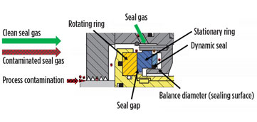
Contamination of dry gas seals through process gas. Two key elements within a dry gas seal are significantly affected by contamination. One is the 3-µ to 5-µ gap between the stationary and rotating seal rings. The rotating seal ring has integrated grooves to generate a gap between the seal rings and to provide a stiff gas film between them during operation. The second is the dynamic seal used on the stationary ring to compensate for compressor rotor axial movement in relation to the compressor case. This axial movement is caused by varying loads on the compressor rotor, as well as by vibration. Changes are also seen in axial position with case expansion from heat and pressure. It is critical to effectively manage all of these factors with the dynamic seal. This can be accomplished only when the stationary seal ring moves unhindered to maintain the gap between the seal rings (Fig. 1).
 |
|
FIG. 1. Dry gas seal components. |
For reliable, trouble-free operation of dry gas seals, the seal gap and dynamic seal must not be contaminated. The purpose of the seal gas is to provide quality gas to the seal. This gas cannot contain particles that will expand the seal gap or clog the gas grooves, and it cannot cause contamination that would affect the operation of the dynamic seal. To ensure that quality gas is delivered to the seal, a source gas is taken from the discharge of the compressor, passed through filters or a gas conditioning system, and then sent through a flow control system and into the seal cavity. The seal gas creates an ideal environment for the seal to operate reliably.
Seal gas flow is simple to achieve during operation, due to the higher discharge pressure compared to the suction pressure typically present in the seal cavity. The challenge occurs during other compressor operating conditions, where little to no differential pressure exists between the discharge pressure and the seal cavity pressure, disabling the production of sufficient seal gas flow. Such instances are common during compressor pressurization, startup, pressurized hold and other transient conditions. At these times, dirty process gas is allowed into the seal cavity, which affects the seal gap and the dynamic seal.
Although the product in a compressor is typically considered to be clean gas, the cleanliness of the process gas is much different than that required by the seal. When gas temperature or pressure changes, components in a gas can turn to liquid. Untreated process gas negatively impacts seal operation and reliability. The seal cavity and seal become contaminated with gas that has particles larger than 3 μ and gas components that are liquid or turn into liquid as the gas leaks through the seal gap; this leads to seal failures.
Contamination for a dry gas seal is split into two categories: particle contamination and liquid contamination. The following sections discuss the effects of seal contamination by each.
Contamination by particles. When small-enough particles (less than 3 μ) enter the seal, they blow through the seal. Larger particles become trapped inside the grooves or seal gap. If the particles become trapped in the grooves and build up, then the seal loses its effectiveness to maintain the seal gap. When larger particles are forced through the seal rings, they will open the seal gap or damage the seal rings. All of these contamination scenarios lead to high seal leakage.
 |
|
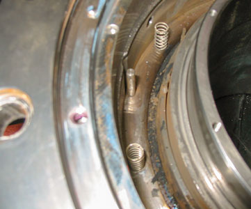
FIG. 2. Debris that will hinder axial movement. |
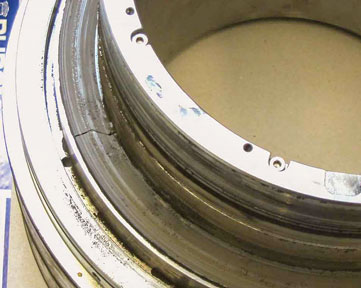
In addition to the sealing gap, the dynamic sealing element is also affected by particles. The dynamic sealing element is an O-ring or an elastomer-free sealing device between the stationary seal ring and a stationary sealing surface (balance diameter). If there is any accumulation of debris around the dynamic sealing element, then the stationary ring axial movement is hindered (Fig. 2). A sticky dynamic seal will open a flow path around the seal ring, which increases the seal leakage. The sticky dynamic seal also eliminates the seal gap, causing the rotating and stationary rings to contact, thereby producing erratic leakage. Eventually, sufficient damage is caused and the seal fails (Fig. 3).
 |
|
FIG. 3. Damaged seal due to poor axial movement. |
Adequate seal gas filtration, conditioning and seal gas flow are key factors to prevent this type of contamination from entering the seal. Whenever pressure is present in the compressor, it is critical to maintain quality seal gas flowing into the seal cavity.
Contamination by liquids. As mentioned previously, if the temperature or pressure of a gas changes, then components in the gas will turn into liquid. When a compressor is hot during normal operation, the operating temperature ensures that the seal gas remains in a gaseous state for most applications. All components remain in a gaseous state as the gas flows from the discharge tap through the seal gas system, into the seal cavity and through the seal, decreasing from discharge pressure and temperature to atmospheric pressure and temperature. As the gas flows through the entire system, dropping in pressure, the gas temperatures can decrease even more due to the impact of the Joule–Thomson effect (Fig. 4).
 |
|
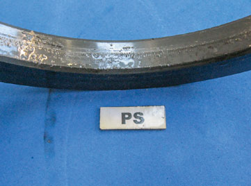
FIG. 4. Liquids formed from components in gas. |
A bigger concern arises when the compressor is not running, as the gas in the seal cavity can cool to the ambient temperature. At this lower temperature and suction pressure, the gas conditions will cause some gas components to turn into liquids or form liquids as the gas pressure drops across the seal gap to atmospheric pressure. To determine when components in a gas turn into liquid, a dewpoint analysis must be completed on an accurate gas composition.
When liquids enter the seal gap or form in it, high shear forces that generate heat are created. The heat produced leads to gap instability, causing contact between the rotating and stationary seal rings, thereby damaging them and leading to a seal failure. If a failure does not occur during operation with the liquid contamination, then the seal will fail at the next start due to increased shear forces on the seal rings, or shortly thereafter due to the heat generated between them. Liquid contamination occurs when gas dewpoint is not considered, when a dewpoint analysis is not completed, when an inaccurate gas composition is used to complete the dewpoint analysis, or when unconditioned seal gas is allowed in the seal cavity during transient conditions.
Two key strategies to prevent seal failures related to liquids are (1) effectively conditioning seal gas to ensure that no liquids form in the seal cavity or seal gap, and (2) preventing process gas that has the possibility of forming liquids from entering the seal cavity. For both particles and liquids, it is of utmost importance to maintain seal gas flow into the seal cavity, so that the ideal seal environment is produced. This ensures that particle or liquid contamination will not enter the seal cavity or seal, which would reduce its reliability.
Contamination in pressurized standstill conditions. One condition associated with the loss of seal gas flow is pressurized standstill. When a compressor is stopped, it is held pressurized for a specified length of time. This allows the compressor to be placed back into operation quickly, if needed. If no means are provided to maintain seal gas flow during this time, then process gas leaks into the seal cavity, contaminating the seal. To minimize the amount of process gas entering the cavity, the compressor is vented after a short period of time. As stricter environmental regulations make the venting of a compressor more challenging without penalties, this procedure has become more difficult. Instances are also seen where a compressor must stay pressurized for extended periods of time to ensure a quick restart to respond to varying demand. If the seal is not effectively protected, then seal failures commonly occur and seriously affect the dependability of the equipment for meeting production requirements, profitability and environmental regulations.
As identified previously, particles in the seal gas or the seal cavity, or liquids that form in a seal gas, are the root causes of the majority of seal failures. To prevent these failures from occurring, it is essential that a clean and quality seal gas is provided to the seal. This maintains a reliable seal that will not fail because of standstill conditions and that prevents failures when restarting (or shortly after restarting) a compressor.
Seal gas flow must be maintained to prevent dirty or wet process gas from entering the seal cavity. A common way to maintain seal gas flow is with a seal gas booster. Typical seal gas boosters are driven by air, but these boosters are not the correct equipment for the application. As a minimum flow is required to ensure a clean seal cavity, a piston-type booster at or beyond its cycling capacity will deliver the required flow, which leads to poor reliability and extreme maintenance requirements. Typically, piston-type boosters do not achieve a satisfactory safety margin above the minimal flow, and sometimes they are even challenged to provide even a sufficient flow. To deliver sufficient flow, multiple units are typically required. Another downside to piston boosters is the amount of instrument air consumed during use. If multiple units are incorporated to meet sufficient seal gas flow, the air demand becomes even more challenging.
To give an idea of the air requirement and how many units should be provided to effectively support the application, an example for a pipeline application encompasses:
- Shaft size: 150 mm (5.9 in.)
- Pressure: 70 barg (1,015 psig)
- Temperature: 23°C (73.4°F)
- Required flow for 5 m/sec (16.4 ft/sec) at twice the labyrinth clearance: 389 Nm3/hr (229 sft3m)/seal–778 Nm3/hr (458 sft3m) for two seals on a beam compressor
- Output of piston booster at 90 cycles/min: 332 Nm3/hr (196 sft3m)
- Drive air required for one unit: 62.6 Nm3/hr (36.8 sft3m).
Based on the size and operating condition for this example, seal gas flow for each seal is more than the output flow produced by one piston booster. To meet the recommended flow for two seals, three boosters should be used. This provides a safety margin to ensure that even unforeseen circumstances are managed effectively. The air utility needed for these three boosters to deliver the recommended gas flow is 132.5 Nm3/hr (78 sft3m).
 |
|
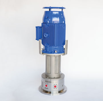
FIG. 5. Centrifugal seal gas booster.a |
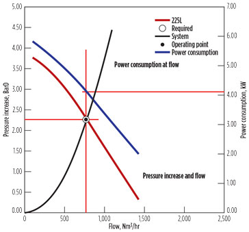
A centrifugal booster (Fig. 5) was developed to provide sufficient seal gas flow, reliability and simplicity to customers. As the centrifugal booster is electrically driven, minimal capital and space are required compared to a piston booster and its associated equipment for utilities to support its operation. The performance of a centrifugal booster and utilities for supporting the same application include 778 Nm3/hr (458 sft3m) of output and power consumption of 4.1 kW (Fig. 6).
 |
|
FIG. 6. Centrifugal booster performance.b |
Takeaway. The industry has confirmed that contamination is the leading cause of dry gas seal failures. As identified in this article, if process gas or inadequately conditioned seal gas is provided to a dry gas seal, it will affect the seal reliability and lead to failures.
The most effective prevention for failures is a reliable seal gas booster. Piston-type boosters are characterized by costly supporting equipment, high maintenance and poor reliability. However, the use of a centrifugal seal gas booster can help maintain a compressor in an unlimited pressurized hold until venting or a compressor restart is absolutely necessary, mitigating concerns of seal failures. Centrifugal boosters are a reliable, cost-effective means of supporting dry gas seals and improving compressor reliability, increasing profits and preventing emissions. GP
Notes
aPhoto courtesy of EagleBurgmann
bThe performance of the centrifugal booster is based on the EagleBurgmann RoTechBooster 225L-120.
 |
Glenn Schmidt is a Senior Sales Director for Turbomachinery Solutions with EagleBurgmann. He provides technical and sales support related to dry gas seals, wet seals and seal systems. His 22 yr of experience with seals include assisting with the development of products for sealing applications and providing input as a member of the API 692 standard for dry gas seals.


Comments