
Debottlenecking of existing oil-gas plants brings significant economic benefits
K. Majumdar, Director, Process Solutions Inc., Calgary, Canada
In today’s challenging economic conditions, the debottlenecking of existing oil and gas plants appears very attractive. Most plants have some intrinsic, though mostly hidden, opportunities to boost their production capacities and efficiencies through troubleshooting and debottlenecking. These efforts can be carried out quickly and safely, at a fraction of the cost required to build new facilities of equivalent capacity. Valuable guidelines are offered here for debottlenecking operations, using a successful, real-life case study as an example.
It has been more than 2 yr since the meltdown in the petroleum industry that started in mid-2014, bringing oil prices crashing down from the $100/bbl–$120/bbl range to around $30/bbl–$40/bbl. Natural gas prices quickly followed suit. As of the time of publication, no solid sign of recovery is in sight.
To survive this extraordinary downturn, most companies have been seeking quick means to bolster the dwindling bottom lines on their balance sheets. The primary ways to achieve this goal are to boost plant production (and, thereby, revenues), reduce production costs, or both. In this volatile market, not many companies are willing to shell out large amounts of capital to finance new projects, or even a major expansion of an existing facility. What, then, becomes the most economically attractive and feasible option for raising the bottom line?
The good news is that options are still available to oil and gas processors to implement such plans without making large investments. One such option is to do a bit of “treasure hunting” in their own backyards—i.e., looking for inconspicuous opportunities that are already present in their existing plants.
Experience shows that most processing plants do have a number of hidden opportunities that can be easily capitalized on to better the company’s financial health. This option typically does not require major changes or large investments. Capitalizing on hidden opportunities usually requires a fraction of the cost and time required to build a grassroots facility of equivalent capacity. If such opportunities are discovered in an existing plant, the owner is unlikely to hesitate to reach for this “low-hanging fruit.”
Where and how to find hidden opportunities. Most plants have sweet spots, or “opportunity packs,” from which such initiatives can be developed. However, constraints or bottlenecks may hold back their productive exploitation. Only experienced eyes can recognize and weigh the worth of these opportunities against the operational challenges present in a brownfield plant environment.
Four such prospective opportunity packs include:
- Feed composition or product quality no longer match the original design and purpose of the plant. If proposed changes are favorable, they often signal a major scope for enhancement, with minimum required physical changes to the plant.
- As a standard practice, a 10%–20% over-design margin is provided in most process plants during initial design. This margin may still be entirely, or partly, available for utilization if some minor to moderate changes are made to existing processes and equipment.
- If some existing processes and equipment are found to be inefficient, costly and/or outmoded, their upgrade or replacement may directly increase capacity and efficiency, and reduce OPEX.
- A small number of underperforming, high-maintenance equipment is often found to undermine an entire plant’s productivity. This equipment should be considered for upgrading or replacement to increase the plant’s reliability, availability and maintainability (RAM).
These opportunities can be realized through troubleshooting and debottlenecking. Such projects typically start with a test run that pushes the plant to its limits, with an occasional adjustment of equipment and operating parameters, based on the judgement of operating personnel. These steps should be followed by a comprehensive feasibility report that includes a cost-benefit analysis, which will help develop a work plan for the entire program.
An exemplary case history. A successful debottlenecking project in a gas treatment and NGL plant resulted in a substantial capacity increase of 33%, or one-third of the plant’s original nameplate capacity of 450 MMscfd. At this plant, a number of crippling process and equipment problems were redressed to push the plant’s onstream factor from a range of 90%–94% to as high as 96%–97%, bringing a significant financial benefit.
The execution strategies applied demonstrate the importance of good planning and the depth of technical involvement required to carry out a successful debottlenecking project at a running plant. The details of this study are shared to guide and assist plant personnel wishing to undertake debottlenecking projects in the future. Although the referenced plant is a gas plant, the strategies and techniques used can be applied to debottlenecking efforts for any process plant, be it an oil processing or chemical production plant.
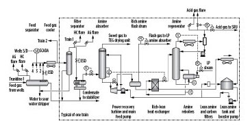
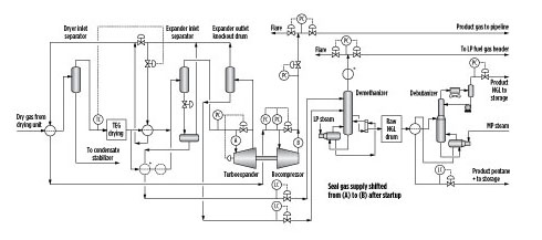
The debottlenecking project was executed in four stages, with one opportunity pack implemented per stage, and it was completed in record time. Schematics of the major process units are shown in Fig. 1 and Fig. 2.
 |
|
Fig. 1. Process schematic of gas separation and sweetening unit. |
 |
|
Fig. 2. Process schematic of TEG dehydration and NGL recovery unit. |
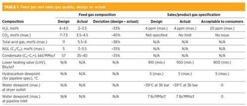
Stage 1. Typically, opportunities in this pack became visible right after a close review and analysis of data and past records. In the referenced plant, a major difference was observed in the feed stream from what was considered in the design; H2S was decreased by 40%–50% and condensate was reduced by 35%–40%.
Sales/product gas quality was also found to be over-specified in the design, compared to what customers required and what was outlined in the supply contract. Approximately 60%–90% of sales gas was consumed by local power and desalination plants, which could accept up to 50-ppm H2S, with no stated limit on CO2, provided that the minimum heating value requirement of 910 Btu/scf was met.
The gas injection compressors for enhanced oil recovery (EOR) were another main consumer. These compressors could accept H2S of similar quality but required no limit on CO2, as long as the gas was dry, as specified (Table 1).
 |
Since the deviations were on the lower side, a large opportunity was foreseen for this plant. A 10% increase in capacity appeared to be possible by changing some operating parameters and process conditions. Hardly any physical changes in plant and equipment, or any capital investment, was envisaged. These items were chosen for Stage 1 since they could be completed quickly, and the economic returns could begin earlier. Due to a reduction in acid gas content (H2S + CO2) in the feed gas and higher H2S allowance in the sales gas, minor changes to processes and operations were adequate to achieve the target:
- The H2S specification in the sales gas was raised to 20 ppm from the original 4 ppm. Accordingly, the diethanolamine (DEA) circulation rate was reduced by 30% to match the changed conditions. This change also reduced the duty of the circulation pumps, aerial coolers and the regenerator section, resulting in significant steam and power savings.
- The steam controller and valve were tuned and recalibrated for smooth operations matching the reduced steamflow rate to the regenerator reboilers.
- No change was required to the downstream units [e.g., the dryer, chillers, turboexpander, NGL recovery and fracing units, condensate stabilization unit, sulfur recovery unit (SRU), etc.] which were found to have adequate margins from their design. Condensate, NGL and sulfur content in the feed stream were lower than in the design.
Stage 2. The objective of this pack of items was to capture most of the 10%–20% margin added during the plant’s design stage. The performance test carried out following the completion of Stage 1 reconfirmed the presence of these margins. The new target was set for a 10% increase over Stage 1 capacity by deciphering major bottlenecks:
- The amine absorber tower foamed severely at a high flowrate, resulting in high amine loss, off-spec product and high flaring. The problem originated from aerosol/mist formation at high velocity in the well flowlines that escaped the separators and filters and reached the tower. The issue was solved by reducing the separator high-liquid level (HLL) and replacing the demister pads and filter elements with high-efficiency pads and elements with improved design.
Continuous dosing of a small amount of antifoam agent was also implemented, alongside the existing shock-dosing system, to combat the high-foaming situation. The frequency of laboratory foam tests (i.e., height and breakdown time) for amine samples was also increased to acquire advance warning of foaming tendency. - Due to the increase in moisture load to the dryer at higher feed rates, dry gas specification became difficult to meet. The load was externally reduced to the pre-debottlenecking level by decreasing the dryer inlet temperature from a range of 30°C–32°C to 28°C by adjusting the flowrate of cold streams to the upstream cross-heat exchangers.
Glycol carryover from the triethylene glycol (TEG) contactor also increased at high velocity. The tray downcomers were found to be limiting, causing poor vapor-liquid separation and high carryover. All existing trays were replaced by new trays with more bubble caps and wider downcomers. The demister pad was also replaced with a thicker and more efficient type to reduce liquid reentrainment inside the pad. - High erosion, and the recurrent failure of the high-pressure absorber level control valve (a tiger-tooth-type valve), made absorber operation difficult. The erosion often required unplanned shutdown of the absorber for repair or replacement. The problem resulted from severe cavitation inside the valve due to large pressure drop (> 50 bar). The problem was finally solved by replacing the existing valve with a Q-ball-type valve and by introducing a choke tube upstream.
- The turboexpander-recompressor (TE-RC) set suffered a design snag from the beginning that prevented the attainment of rated capacity. The Joule-Thomson valve that operated in parallel with the expander took the balance load, after minor process adjustments. Although NGL recovery dropped marginally, the hydrocarbon dewpoint of the sales gas was still met. The TE-RC was later refurbished in Stage 4 by changing the rotor.
Stage 3. The enhancement target for this opportunity pack was set at 10% over the Stage 2 target. The test run performed after Stage 2 confirmed that most of the major equipment, such as the absorber, regenerator, reboilers, coolers, glycol contactor tower, chilling unit, NGL unit, SRU, major pumps and heat exchangers, contained the potential to meet the expected target (i.e., from the original nameplate capacity of 450 MMscfd to 600 MMscfd).
However, some equipment, process systems and piping required refurbishment and upgrading to ensure efficient, safe and sustained operation, which required additional investment. Based on a “remaining life” assessment conducted at that point, as well as a lifecycle cost analysis of benefits and costs, proposed changes were found to be very attractive. Process changes included:
- DEA was replaced by generic methyl diethanolamine (MDEA) due to the latter’s ability to remove H2S selectively over CO2. The amine circulation rate could be reduced since less CO2 was to be removed by amine, and the sales gas specification was relaxed from 4 ppm to 20 ppm. As a result, steam and power requirements dropped by more than 30%. Sales gas yield per unit of feed gas flow increased due to the higher amount of CO2 slipping into the sales gas. This scenario allowed higher gas flow to the gas injection system for EOR. Only the steam control loop and valve needed minor modifications to operate efficiently at a lower steam flowrate.
- H2S in the acid gas stream (i.e., the feed to the SRU) increased from 30% to approximately 45%, due to lower CO2 coabsorption by MDEA. This led to increases in capacity and performance of the SRU. By default, the problem of frequent flame failure in the sulfur burner due to the low H2S concentration in the acid gas was also eliminated.
- Due to lower CO2 removal by MDEA, the acid gas volume entering the SRU remained nearly unchanged, despite an increase in plant feed of 33%. Total sulfur (H2S) load to the SRU also remained nearly unchanged, as the H2S in the feed gas was lower than that considered in the design. Hence, no tangible impact was recorded on the SRU sulfur burner, catalytic reactors, waste heat boiler condenser, incinerator, etc. Only a few minor changes and adjustments were required for the SRU.
Equipment and hardware changes included:
- The 21 trays in the amine absorber were replaced by stainless steel (SS) random metallic tower packing (RMTP) of 50-mm diameter, which raised absorber capacity by 40%. Post-weld heat treatment, hydrostatic tests, recertification, etc. were avoided by using redundant tray supports, hangers, rings and other equipment already present in the tower.
- In the glycol contactor, all seven trays were replaced by SS structured packing. Glycol flowrate was increased by 15%–20% by adjusting the speed and stroke of the reciprocating glycol feed pumps. Stripping gas flow to the regenerator bottom drum was also increased marginally.
Stage 4. The remaining problems that eroded the plant’s onstream factor to 90%–94% were tackled in this stage. At least 96%–97% was expected to be achievable, since the plant underwent no annual complete shutdown. Instead, it underwent modular shutdowns for inspection and planned maintenance. Some of the problems solved in this stage may be typical of other process plants:
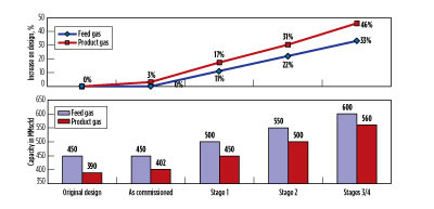
- Expander-recompressor lube oil viscosity continuously dropped during operation (normal: 30 cst at 40°C) due to the absorption of hydrocarbons (C4+) from heavy seal gas, tapped from the inlet side of the expander. The off-skid oil filtration-conditioning unit could not resolve the problem. By shifting the seal gas tapping from the expander’s inlet side to the outlet of the recompressor (Fig. 3), the location changed from (A) to (B), and the issue was resolved.
 |
|
Fig. 3. Enhancements after completion of each debottlenecking stage. |
- The inlet guide vane of the TE-RC often jammed during operation due to hydrate formation on the inlet guide vanes. An investigation confirmed that, occasionally, moisture breakthrough occurred from the upstream dryer, which the faulty online moisture analyzer failed to detect. The moisture analyzer was replaced with a more efficient model, and periodic calibration was implemented to ensure that both dryer and analyzer performed satisfactorily. Also, the continuous injection of small doses of methanol at the inlet of the chillers and the expander was resumed, eventually eliminating the problem.
- Frequent regenerator-reboiler tube cutting at the baffle plates was a major problem that could not be solved, even after attempting several alternate designs, such as rod-baffle design, change of tube pitch and arrangement, and change in number of plates. The problem was found to originate from unnoticeable tube thinning due to corrosion from DEA. This corrosion occurred in the pre-MDEA period, when residual H2S in lean amine and steam temperature (superheat) were higher than the ideal values.
After the transition to MDEA, stringent control of residual H2S, and reintroduction of the steam desuperheater, the corrosion rate dropped to less than one-fifth of the previous level, and the tube-cutting problem disappeared. Use of SS tubes could have been another viable solution, but this was not considered since the feed gas often contained high chlorides from the wells. At high reboiler temperatures, these chlorides are highly detrimental to SS. Also, SS was determined to be 2.5–3 times costlier than carbon steel (CS).
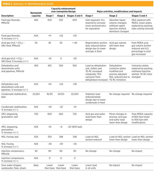
The results of the four stages of debottlenecking are shown in Table 3 and Fig. 3. The debottlenecked plant has been running for more than 20 yr at 133% (150 MMscfd over its nameplate capacity), at a much higher efficiency and plant availability, and without any major incidents, lost-time injuries or extended shutdowns.
 |
HSE issues in debottlenecking. Any debottlenecking operation invariably results in some amount of departure from the plant’s original design premises and operating envelope. For this reason, the original safety procedures, protection philosophy, test certificates, etc., will require a fresh review. The following health, safety and environmental (HSE) initiatives brought an impeccable safety record to the referenced project:
- Hazard identification and hazardous operations reviews are conducted at various stages, including reviews of pressure and temperature diagrams, pressure and protection systems, material safety data sheets, emergency flare and disposal systems, etc., at the beginning and end of the debottlenecking project.
- Work inside the live plant area was minimized through careful planning; unavoidable activities were only performed after proper risk assessment was conducted, and a mitigation plan and precautionary measures were put into place. Permit-to-work protocol was strictly followed for all work carried out inside the live plant.
- The health of all equipment subjected to high pressure, high temperature and/or H2S was assessed by using visual inspection, ultrasonic thickness testing, hydrostatic testing and other measures.
- Original operating and maintenance manuals and procedures were reviewed and updated.
Lessons learned from case study. This model case demonstrates how good planning and effective technical applications can bring major benefits to an existing process plant through low-cost, fast-track execution. Several important lessons can be taken away:
- A test run, followed by a comprehensive feasibility study, is essential at the beginning of any debottlenecking project. A test run after each debottlenecking stage is also necessary to assess the performance of the completed stage and to fine-tune the plan for the next stage.
- Troubleshooting of longstanding problems is one of the prime requirements for success in any debottlenecking program. The upgrade and replacement of old and outdated processes and equipment with safer and more efficient items should be considered wherever techno-economic justification favors it.
- Since debottlenecking is a brownfield job that is performed, in most cases, without completely interrupting the operation of the existing plant, thorough planning is important to minimize hot work. This can be accomplished by taking advantage of the plant’s scheduled shutdown windows.
- For extensive debottlenecking programs, the execution schedule should be broken up into multiple stages, instead of one long program. This structure allows early economic returns from the work already completed. It also minimizes production loss and the risk of working inside the live area. Additionally, breaking the project into stages allows work items that require procurement of long delivery components to be executed in the later stage(s).
- Recertification of equipment and piping should be minimized by keeping their original design conditions unchanged (e.g., pressure, temperature, etc.) and by avoiding hot welding. Only available cleats, rings, hangers, etc. should be used for modification.
- Accommodation of new equipment per engineering standards and practices in already congested or modular plants may be a problem. Any issues should be preemptively considered and addressed in the early stages of planning.
- Regulatory clearances and requirements should be considered and applied for well ahead of time.
Challenges not to be underestimated. Some seemingly innocuous and trivial challenges may deter debottlenecking ventures, if not addressed early. Examples of such challenges include:
- A remaining life assessment of the plant should be performed at the beginning, to justify any major additional financial stake and long-term expectations.
- Before launching the debottlenecking project, the availability of reliable and up-to-date engineering drawings, documents and specifications (i.e., process flow diagrams, piping and instrumentation diagrams, line lists, layout and piping drawings, quality assurance and quality control documents, etc.), depicting all past changes for the existing process plant, must be ensured. Missing or incomplete documentation may become a major issue later on, requiring substantial time and cost to collate and/or recreate them.
- Additional raw materials, chemicals and other resources needed to run the plant at enhanced capacity should be assessed and arranged in advance.
- Last, but not least, a successful debottlenecking project should conclude with the updating and consolidation of all drawings, manuals and engineering documents reflecting “as-built” condition. This process is important in brownfield projects like debottlenecking. Plant personnel should have reliable resources within their reach to run and maintain the plant safely and smoothly, long after the project team and contractors have left the site. The old drawings and documents should either be destroyed or clearly stamped “void” or “superseded,” and put out of circulation. GP
 |
Kumares Majumdar holds a BSc degree in chemical engineering and has more than 45 years of work experience in the oil, gas and petrochemical industries in design, engineering, operations and commissioning. He has also developed a wide range of improvement and optimization ideas, conceptualization and planning processes, feasibility studies, troubleshooting procedures and consulting work. He has worked with leading international engineering (EPC) and operating companies in Canada, the UK, the US, the UAE, India and North Africa. He is a registered professional engineer in Canada and is presently working as a consultant to leading EPC firms and operating companies. He has authored and presented numerous papers in technical journals and at symposiums. Mr. Kumares can be reached at kumares.majumdar@gmail.com.


Comments