
Design and select a gasketed plate-type heat exchanger for gas processing
R. Pramanik, Fluor Daniel India, Gurgaon, Haryana, India
In recent years, plate-type heat exchangers (PHEs) have emerged as a viable alternative to shell-and-tube heat exchangers (S&THEs). The PHE, with its ability to optimize thermal performance, has made close approach and temperature cross-applications economically feasible where they are not economical or practical with S&THE designs.
However, unlike their S&THE counterparts, the design and engineering of PHEs is generally carried out by the supplier, and not by the front-end engineering design (FEED) and detailed engineering companies. This scenario sometimes makes it difficult for the engineering companies to optimally specify the requirements of the PHEs, leading to long deliberation at the detailed engineering stage and resulting in missed project deadlines.
The basic design and selection issues for gasketed PHEs, the most common type of plate exchanger, are discussed here. If addressed carefully by the engineering contractors in the early stage of development of the specifications for gasketed PHEs, proper design can go a long way in minimizing changes during the detailed engineering stage.
Issues related to PHE specification. Several issues must be addressed while developing PHE specifications.
Design pressure. The design pressure is governed by the material of the gasket being used and is generally limited to approximately 16 barg. However, in some cases it can be as high as 25 barg.
Design temperature. Like design pressure, design temperature is also limited by gasket material. It varies from approximately 135°C with nitrile butyl rubber (NBR) to approximately 180°C with ethylene propylene terpolymer (EPT) rubber, the two most common forms of gaskets. However, the use of special gasket material (compressed asbestos fiber) can increase the design temperature to approximately 260°C.1
Type of fluid. A PHE can handle low-density vapors, but it should not be coupled with high flow. The combination will either result in very large plate spacing, thereby making the heat transfer ineffective, or it will require a very high pressure drop with standard
plate spacing.
Plate material. Other than the ductility, the plates in PHEs are not limited by the material of the plate (which is primarily governed by the type of service) and can be fabricated from many different materials (e.g., stainless steel, titanium, hastelloy, incoloy 825, nickel 200, monel 400, aluminum brass, tantalum, etc.).
One of the most common uses of PHEs is in seawater service. A number of alloys have been successfully used as plate material in seawater service. Copper-nickel alloys and the 300-series austenitic stainless steels are normally considered minimum starting points for materials selection in seawater, with super austenitic stainless steels, nickel-based alloys, and titanium specified for the more severe services.
Crevice corrosion is a major consideration in component design and alloy selection for seawater service, and will often dictate materials selection when crevices cannot be avoided. Grade 1 titanium, being the purest and most malleable, is widely used in PHEs.
Gasket material. For PHEs, the standard gasket materials are EPT and NBR. EPT is normally used for non-fatty/oily applications, and NBR is used for oil/fat applications. However, an oil/fat application may have a low fat content, making the application more suitable for EPT rather than NBR. Other rubbers used for PHEs are hydrogenated nitrile rubber (HNBR) and fluorocarbon rubber (FKM).
At high temperatures, the rubber will be attacked faster by the chemicals in use, as well as by the surrounding oxygen. The oxidation process will either make the rubber harder (most common) or make it softer (less common), or both at the same time. Either way, the change in properties will reduce the performance. All rubber materials have a maximum continuous temperature. To maintain good performance and to achieve a reasonable lifetime, this temperature should not be exceeded.
At low temperatures, stiffness increases and elasticity decreases. This fluctuation influences the sealing force of the gaskets. All rubber materials have a certain lowest temperature that must be exceeded for the material to perform well enough as a gasket.
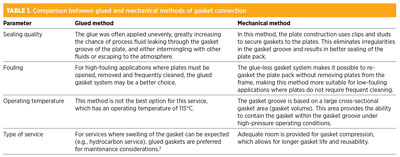
Method of gasket connection. The gaskets are secured to the plates either by glue or by mechanical means. Table 1 shows a comparison between the two methods of connection.
Gasket testing. If the vendor lacks experience in the use of the proposed gaskets for an application, then the gasket should be subjected to an immersion test to measure gasket swelling, hardness and susceptibility to chemical attack. The test should be conducted at the operating temperature, using a piece of the specified gasket material with a maximum thickness of 8 mm. The minimum duration of the test is 15 days. The gasket hardness change should not exceed 15 international rubber hardness degrees (IRHDs) for fluoropolymers and 10 IRHDs for others. The volume change should not be more than 15%.2
Glue testing. If the vendor lacks experience in the use of the proposed glue for an application, then the glue should be subjected to an immersion test to measure the glue strength and susceptibility to chemical attack. The test should be conducted using a 100-mm piece of the specified gasket, at operating temperature, for a duration of 15 days. Half (50 mm) of the gasket should be glued to a surface that is equivalent to the gasket-groove surface of the proposed plate—i.e., a smooth surface should be used if the proposed plate’s gasket-groove surface is smooth, and a corrugated surface if the proposed plate’s gasket-groove surface is corrugated. The final peel strength, in newtons, should be five times the gasket width in mm (or in lb-force, 28 times the gasket width in inches).2
Fouling margin. In PHEs, as in other compact heat exchangers, it is common practice to provide a fouling margin, which is the amount by which the surface area must be increased to account for fouling. One issue that is hotly debated during the preparation of PHE specifications is the fouling margin. In most cases, the fouling margin tends to be overspecified for PHEs, as the underlying differences in the flow patterns between PHEs and S&THEs are ignored.
Several issues should be kept in mind when specifying the fouling factors of PHEs:
- Turbulence and wall shear stress are the two most important parameters affecting fouling. The wall shear stress, which is directly proportional to the friction factor,1 is much higher in PHEs. Turbulence is also much higher in PHEs compared to S&THEs. Both of these factors result in a lower propensity to fouling in PHEs as compared to S&THEs.
- PHEs are made from corrosion-resistant materials. Therefore, the chances of fouling due to corrosion are much lower than those of conventional S&THEs.
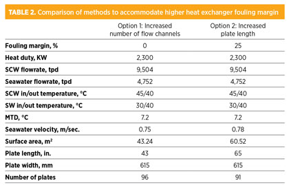
- A higher fouling margin requires a larger surface area, which can be provided either by increasing the surface area of each plate (by selecting plates with higher length and width) or by increasing the number of flow channels, or both. Table 2 shows a comparison of how additional fouling margin can be accommodated by increasing plate length instead of the number of flow channels. An increase in either the number of flow channels or the plate width will result in lower velocity, leading to an infringement of minimum velocity constraints. This increases the chances of fouling and defeats the purpose of the additional margin.3
The required fouling factors to be specified for PHEs are always lower than the corresponding values for S&THEs (e.g., as recommended in TEMA4), and the fouling margin in a typical PHE never exceeds 20%–25%.
Several recommendations for fouling margins are available in API-6612 and HTRI.1 In the absence of field data, the following guidelines may be referred to when specifying a reasonable fouling margin for the PHE:
- API-662, appendix A:2 A minimum of 10% fouling margin should be included. For crude oil service, this margin may need to be increased to 25%. Over and above the fouling factor, wall shear must also be specified since wall shear stress provides a good indication of fouling tendency in a PHE. A minimum wall shear stress of 50 Pa is recommended.
- HTRI:1 Consider a fouling factor that is approximately 25% of the corresponding value for S&THEs (given in TEMA4), or use fouling factors as recommended in HTRI report PHE-1.
Sparing philosophy. In the case of a PHE having multiple units in parallel to cater to a large heat duty and requiring frequent maintenance (e.g., seawater vs. closed-water service), keeping a greater number of units in operation with higher fouling margin, and a lower number of units in spare to avoid downtime, may sometimes be counterproductive since more fouling margin may actually result in higher propensity to fouling, therefore leading to greater-than-expected downtime. Use of sparing philosophy in this type of service should be selected carefully to minimize the capital and operating costs.
Plate thickness. Plate materials in PHEs are selected to resist corrosion. For this reason, it is not intended to include a corrosion allowance. The thickness of the plate is entirely dependent on the differential pressure across the plate, the nature of plate corrugation and the ductility of the plate material. It generally varies from 0.5 mm to 1 mm, with the minimum being specified
by API-662.
Plate gap. The typical gap between adjacent plates varies from 2.5 mm to 5 mm, depending on the design pressure and the limitation of the plate fabrication technology. In applications where process media contain particulate matter, or when large amounts of scaling can occur, careful consideration should be given to the free channel space between adjacent plates.
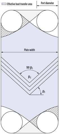
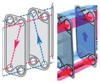
Plate corrugation. Corrugation is quantified by the plate’s Chevron angle (β). The heat transfer and pressure drop capabilities of a plate are governed by β. Nomenclature of β varies—β1 or β2, as shown in Fig 1. Note: β2 = 180 – β1. Plate corrugation (as defined by β1) generally varies from 25°–65°, with the corresponding values for β2 being 130°–50°.
 |
|
Fig. 1. The heat transfer and pressure |
NTU range of the plate. The number of transfer units (NTU) range is one of the two most important parameters for specifying PHE plates.5 NTU is defined as the ratio of the temperature change of one fluid to the log mean temperature difference across the plates. NTU is related to the overall heat transfer coefficient (U) and pressure drop (ΔP), as shown in Eqs. 1 and 2:5
![]() (1)
(1)
![]() (2)
(2)
where:
L = Plate length
v = velocity through the plate channel.
The actual indices and proportionality constants of the above relations are dependent on β. Depending on the value of β, two types of NTU plates are possible:
- Low-NTU plates: NTU < 1 and β approaches 65° (plate with low obliquity). The friction factor and Nussalt number decrease, resulting in low heat transfer and pressure drop. NTU can be as low as 0.3 for a single-pass PHE handling aqueous liquids.
- High-NTU plates: NTU > 1 and β approaches 25° (plate with high obliquity). The friction factor and Nussalt number increase, resulting in high heat transfer and pressure drop. NTU can be as high as six for a single-pass PHE handling aqueous liquids.
Maximum flow capacity. This second-most-important parameter for specifying PHE plates5 is governed by the size of the port at the four corners of the plate and determines the overall plate dimension, as shown in Fig. 1. The higher the flow, the larger the port diameter and the lower the net heat transfer area available for a plate of a particular geometry. The larger port diameter not only requires a greater number of plates in parallel to cater to a given duty, but it also forces the designer to adopt a plate that is wider than required from a thermal design point of view. These two requirements result in lower velocity and increased chance of fouling.
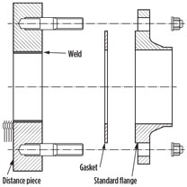
One way to accommodate ports of large diameter (with the maximum being limited to approximately 450 mm) and cater to a very high flowrate (with the maximum being limited to approximately 3,000 m3/hr) without increasing the width of the plate is to use a “distance piece” to stagger the flanged connection directly perpendicular to the plate. A typical distance piece detail is shown in Fig. 2.
 |
|
Fig. 2. Typical detail of distance piece. |
Allowable pressure drop. Since the friction factor of PHEs is much higher than in S&THEs, a greater pressure drop must be specified across a PHE than across a S&THE. However, the utilization of available pressure drop in PHEs is better than in S&THEs; therefore, the overall pressure drop in PHEs will be less than in S&THEs.
Velocity through plate channel. The typical velocity, v, varies from 0.1 m/s to 1 m/s, with the minimum being governed by the wall shear stress of 50 Pa (since a value lower than 50 Pa may lead to frequent fouling of the PHE2), and the maximum being dependent on the available pressure drop.
Flow ratio. The typical geometry of a PHE does not allow for much difference between the flowrates of fluids in adjacent passages without affecting the heat transfer effectiveness. A typical single-pass PHE with maximum heat transfer effectiveness can accommodate a flow ratio between two heat transfer fluids of 0.7 to 1.4. Outside this range, an unequal pass must be adopted requiring a significant LMTD correction factor.
Design issues. Several design constraints must be considered when designing for heat transfer effectiveness and efficiency, as detailed in the following sections.
Flow distribution. Proper flow distribution through a PHE is required for optimum conversion of available pressure drop to heat transfer and must be subdivided into flow distribution through individual plates, and distribution through the entire PHE, to be properly understood.
Distribution through an individual plate. The flow distribution inside a plate is dependent on three factors:
- Port arrangement: The inlet and outlet ports can be diagonal or vertical, as shown in Fig. 3, with the diagonal providing a better distribution.
- Aspect ratio: A higher aspect ratio (length to width) results in better distribution.
- Plate entry loss: Since port areas are the weakest portion of the plate, they require strengthening by restricting or reducing the port area, which increases the losses at the entry and is calculated1 approximately as shown in Eq. 3:
![]() (3)
(3)
where:
Np = Number of passes
Gp = Port mass velocity.
 |
|
Fig. 3. Diagonal vs. vertical port |
The port pressure drop should be approximately 10% of the total pressure drop in a well-designed exchanger.1 This pressure drop can be as high as 25% for single-pass exchangers, but high pressure drop in a multi-pass exchanger will affect the heat transfer.
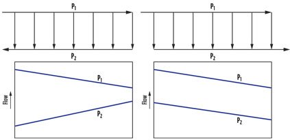
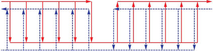
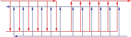
Distribution through PHE. Two types of distribution—U-arrangement and Z-arrangement—are possible, as shown in Fig. 4. Each of these arrangements is characterized by pros and cons. While U-arrangement results in unequal flow distribution in the channel, it requires inlet and outlet ports in the fixed head plate, thereby simplifying piping and maintenance.
 |
|
Fig. 4. U-arrangement vs. Z-arrangement. |
A Z-arrangement, on the other hand, ensures equal velocity throughout the channels, but makes piping and maintenance more complicated with inlet and outlet ports in fixed-head and movable plates, respectively.
When proper distribution becomes as important as the piping and maintenance issues, different types of channels in a U-arrangement are used in parallel for the same flow. The flow across channels is distributed depending on the channel geometries, since the flow across all of the plates remains the same. L-type channels near the movable plate will result in lower pressure drop and allow more flow to pass through these channels, thereby alleviating some of the effects of the improper distribution of a U-arrangement. This arrangement of plates is provided by the PHE supplier as a “plate hanging list,” and the same should be requested during the detailed engineering stage to ensure proper flow distribution through the PHE.
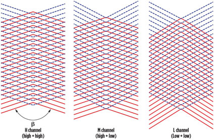
Thermal mixing. This type of mixing combines high-NTU plates with low-NTU plates in correct proportion to optimize the utilization of available pressure drop in heat transfer, thereby avoiding multipass. Three combinations are possible (as represented schematically
in Fig. 5):
- HH (H channel): A channel formed with high-NTU plates on both sides.
- HL (M channel): A channel formed with a high-NTU plate on one side and a low-NTU plate on another. This channel is used when the flowrates of the two fluids are very different. The channel β is taken as the arithmetic mean of βhigh and βlow.
- LL (L channel): A channel formed with low-NTU plates on both sides.
 |
|
Fig. 5. Schematic representation of three types of mixed-plates combination. |
The Heat Transfer Design Handbook4 provides the typical plot of an NTU plate vs. Δp of mixed plates.
 |
|
Fig. 6. Single-pass arrangement. |
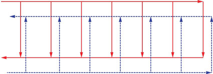
Types of pass arrangement. Sometimes, a pass arrangement is different than the ideal 1–1 pass (Fig. 6) and is adopted to cater to a large variation in flowrates of the two heat exchanging fluids. Two types of multipass are possible, namely multipass with equal passes and multipass with unequal passes, as shown in Fig. 7 and Fig. 8.
 |
|
Fig. 7. Multipass with equal number of passes on both sides. |
 |
|
Fig. 8. Multipass with unequal number of passes. |
No LMTD correction is required for single-pass and multipass with equal passes since the flows are a perfect countercurrent. However, a correction factor is required for multipass when the passes are unequal, as in cases with large, unequal flows that cannot be addressed with thermal mixing. However, this correction is not as significant as that in S&THEs due to lack of leakage or bypass streams.1
Finally, continuous advances in manufacturing technology should be kept in mind when specifying design details. Vendor and user recommendations should be given due consideration before finalizing the selection of gasketed plate heat exchangers. GP
LITERATURE CITED
- 1“A review of the present method of predicting heat transfer and pressure drop in PHEs,” Report PHE-1, Heat Transfer and Research Inc., March 1990.
- 2“Plate heat exchangers for general refinery services,” American Petroleum Institute, API-662, 1st Ed., December 1995; and International Organization for Standardization, ISO-15547, November 2005.
- 3Pramanik, R., “Fouling margin in plate heat exchanger,” Chemical Engineering World, March 2014.
- 4Tubular Exchanger Manufacturer Association Inc., “Standards of the Tubular Exchanger Manufacturer Association,” 8th Ed., 1999, Tarrytown, New York.
- 5Thulukkanam, K., Heat Exchanger Design Handbook, CRC Press, 2nd Ed., 2013, Boca Raton, Florida.
RITABRATA PRAMANIK has more than 29 years of experience in the design and engineering of heat equipment in the oil and gas, petrochemical, LNG, fertilizer, chemicals and power sectors. His experience includes project management, consultancy for both FEED and EPC, supply and lump-sum turnkey work. He has worked with Fluor Daniel India in New Delhi since July 2013.


Comments