
Use integrated analyses in design and operation of LNG systems
J. Valappil, R. Kumar and J. Mumm, Bechtel Oil, Gas and Chemicals, Houston, Texas
The LNG industry has seen tremendous growth in recent years, with several grassroots plants being built around the world. Many of these facilities are being constructed onshore, although the gas field may be located offshore—in some cases, hundreds of km away.
The transportation of the gas and condensate from these offshore fields to the gas processing and LNG facilities introduces several challenges. The pipeline from the offshore field to the shore is characterized by long distances and elevation changes. Any operational disturbances in the upstream pipeline can adversely impact the operation of the gas processing or LNG facility. These impacts include the formation of slugs that can cause severe operational challenges for the inlet facilities of the onshore plant. Accounting for these upstream disturbances in the design of slug catcher and inlet facilities is critical to ensuring reliable facility operation.
The slug catcher in the onshore facility is designed to handle the slugs that result from various operational scenarios. In addition, the inlet facilities, including the stabilizer system, are designed to account for the condensate liquids that must be processed. The proper designs of these units are important for the reliable operation of the entire facility under all conditions. The unit designs are a balance between operational flexibility and capital cost. A design that can handle the volume of slug for all operational scenarios without impacting the operation can be prohibitive from a capital-cost perspective. Therefore, some operational flexibility is sacrificed to design a facility with reasonable CAPEX.
The slug catcher and stabilizer facilities are designed to handle the slug generated during various modes of operation and upset conditions. This is usually accomplished by flow assurance analyses in the early stages of the facility design (front-end engineering or earlier).1 This analysis uses a rigorous model to determine the effects of various operational scenarios. These scenarios include pigging, startup after shutdown, flow ramp-up, minimum turndown and other relevant scenarios. Transient simulation of the pipeline model is utilized to determine the slug arrival time, slug volume and other pertinent information.
Additional benefits are gained by integrating a rigorous dynamic model of the pipeline with a model of the onshore facility. This model helps eliminate assumptions regarding the conditions at the interface between offshore and downstream facilities. The integrated model can also be valuable to establish operational strategies on both sides to account for the various upstream scenarios. This process helps verify the design of the entire natural gas/LNG value chain (from wells to the delivery point). The tradeoffs established during design between capital cost and operational flexibility can be verified in a rigorous manner with this methodology.
A case study is presented where a rigorous pipeline model is linked with a dynamic process simulation model of an onshore LNG plant. This integrated model is used to test various operational scenarios, including pigging and flow ramp-ups. The results are valuable for verifying the design of the individual equipment and units, and for identifying operational recommendations for the entire offshore/onshore gas transport infrastructure and LNG facility.
DESIGN AND OPERATION OF SLUG CATCHER AND STABILIZER SYSTEMS
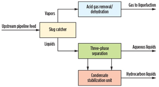
At onshore gas processing facilities, the first step is to separate the gas from the liquids. Slug catchers are used onshore to catch large slugs of liquid in pipelines and to provide a temporary storage buffer. These liquids are then delivered to the liquid processing facility at a suitable rate. These slug catchers may be of the vessel type or the finger type. The finger-type slug catchers are normally preferred for the larger volumes typical in natural gas and LNG facilities. Fig. 1 shows a typical inlet facility in an LNG plant with a three-phase slug catcher. The gas from the slug catcher is sent for further purification and liquefaction.
 |
|
Fig. 1. A typical slug catcher inlet facility configuration in a |
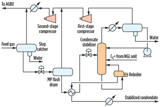
The condensate stabilization system is designed to process the NGL from the slug catcher and produce condensate that meets Reid vapor pressure (RVP) and H2S specifications. The process schematic of a condensate stabilization unit typically used in LNG plants is shown in Fig. 2. Here, the hydrocarbon liquids from the slug catcher are let down to an intermediate pressure in the flash drum. The flash gases are recovered and sent back to the feed gas; then, the liquids are routed to the condensate stabilizer column. The overhead vapor from the stabilizer is compressed and returned back to the feed gas system and the amine unit. The bottom product from the stabilizer column is the condensate product.
 |
|
Fig. 2. A typical condensate stabilization system in a natural |
Upstream scenarios affecting onshore facilities. The design of the slug catcher and inlet facilities must account for the various operational scenarios and disturbances in the upstream pipeline feeding the LNG plant. Several scenarios impact the feed to onshore facilities, especially the slug volume:
- Pigging. Pigging operation is necessary in multiphase flow systems for the purpose of inspection/maintenance and ensuring that the pipeline is clean. When pigging, a liquid slug is created ahead of the pig, which can be challenging for receiving facilities (i.e., the LNG plant).
- Flow ramp-up. The increase of pipeline flow from turndown rates to full rate is a major disturbance for the onshore plant. This disturbance is due to the fact that the liquid holdup in the pipeline is higher at lower rates. As the flow is ramped up, the extra liquid is swept onshore, creating a surge of liquid at the onshore facility.
- Gas field switchover. In several cases, a single LNG plant can be fed from multiple pipelines and wells. Switching of these pipelines or production wells can cause a compositional disturbance that changes the volume of liquid in the pipeline.
- Onshore plant operational upsets. Various operational upsets in the onshore plant can cause the pressure at the slug catcher to vary significantly. This pressure variance can result in changes in the volume of liquid arriving at the onshore facility.
Sizing of slug catcher and stabilizer systems. The sizing of the slug catcher in a natural gas facility is intended for process stabilization, phase separation and storage of the liquid during various operational scenarios. The slug catcher is intended to dampen the effects of flowrate surges and deliver a steady supply of liquid to the production facilities.
The size of the slug catcher is based on the liquid accumulation rate. This can be calculated as Liquid input mass rate – Liquid discharge mass rate = Liquid accumulation mass rate.
The liquid input mass rate is the liquid flowrate entering into the slug catcher. It is dependent on the system operating philosophy, strategies and procedures adopted. Liquid discharge mass rate is a function of the capacity of the control valve and the stabilizer unit. The liquid accumulation rates can be calculated to determine an appropriate size for the slug catcher.
Significant CAPEX savings can be realized by optimizing the size of the slug catcher that is required to handle the slugs and prevent upsets on the downstream equipment. Analysis using multiphase simulation tools early in the design phase can be valuable in optimizing the size.
Stabilizer systems are sized to handle the liquids from the slug catcher to produce NGL products, and are sized for the normal liquid rates, within an appropriate margin. It is impractical to size the stabilizer systems for the maximum liquid rates expected during various upstream scenarios. It is possible to oversize the stabilizer system beyond the normal liquid rate. This scenario reduces the required size of the slug catcher, thereby establishing a tradeoff between the capital cost of the slug catcher vs. the stabilizer system.
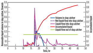
The removable liquid in the slug catcher (Fig. 3) is the volume above the minimum volume required for the slug catcher. The pipeline was initially operating at the steady-state flowrate. It was then shut down and gradually ramped up to the final flowrate.
 |
|
Fig. 3. Various factors that go into sizing the slug catcher |
Tradeoff between capital cost and operability. The design of the slug catcher and inlet facilities should account for the various upstream operational scenarios that can impact the natural gas facility. In many cases, it is not economically feasible to size the slug catcher to handle the maximum slug arrival rate, considering all the scenarios. In these cases, the facility must sacrifice the operability to reduce the slug catcher size and, therefore, the capital cost.
Placing an economic figure on the operability of the plant may prove difficult, but an attempt should be made to account for this figure in economic calculations. The overall design is, therefore, a tradeoff between capital cost and operability.
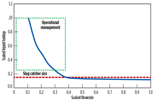
This tradeoff is demonstrated in Fig. 4, which shows the amount of liquid holdup in the upstream pipeline as a function of flowrate. At lower flowrates, the holdups can be large. Performing pigging operation at these low flowrates, or ramping up from these low rates to full rate in a reasonable time, requires a slug catcher that is larger than an optimal one (Fig. 4). This is cost prohibitive, so the more practical approach of performing a pigging operation and ramp-up rate change (continuous, step-mode) should be performed to meet the slug catcher boundary conditions.
 |
|
Fig. 4. Liquid holdup in pipelines as a function of flowrate. |
During ramp-up operation in step mode, slug catcher inventory is reduced after each step. This adds to the ramp-up time, affecting operability. If permissible prior to the pigging or ramping-up operation, the liquid inventory in the system can be lowered by various modes of operation.
To account for many of the upstream scenarios, the onshore facility can be prepared in a number of ways:
- Prepare slug catcher. The slug catcher can be drained to the lowest level and then set at the proper operating pressure to reduce the impact.
- Initiate condensate stabilization. The condensate stabilization unit can be ramped up to maximum production before the arrival of a slug.
- Reduce time in turndown conditions. This decreases the liquid inventory in the pipeline, minimizing the slug volume arriving at the onshore facility.
- Change compositions fed to the pipeline. If feasible, the upstream source composition can be modified to minimize the liquid inventory. This normally means using lean wells before pigging.
- Tailor flow ramp-up to satisfy the slug catcher. The increase in flow from turndown or shutdown to full rate may be tailored to reduce the slug size.
DESIGN AND ANALYSIS METHODOLOGIES
A brief overview of the design methodology normally used for multiphase pipeline systems is outlined in the following sections.
Design using model of upstream pipeline. A rigorous simulation model of the upstream pipeline is normally utilized in the design of the slug catcher in the onshore plant. The model should offer the capability to predict the multiphase flow characteristics to accurately estimate the slug sizes. All the relevant aspects of the pipeline, including elevation changes, are included in the model. Normally, the model is developed as a part of the flow assurance study performed during the early design phase.
The rigorous pipeline model is then used to run steady-state and transient simulations of the various aforementioned operational scenarios. The main information used for sizing is the volume of liquid flows coming from the pipeline to the slug catcher.
In establishing the design and operation of the multiphase pipeline, valuable data can be obtained from such an analysis:
- Steady-state pressure profiles. These profiles are critical to ensure that an adequate flow can be fed to the onshore facility at various pressures. The pressure drop is calculated using multiphase flow correlations.
- Steady-state liquid holdups. The steady-state liquid holdup in the pipeline is important in establishing the liquid volume during turndown conditions. At lower flowrates, the liquid volume is greater. Fig. 4 demonstrates the relationship between flowrate and liquid holdup.
- Slug sizes during various scenarios. Transient analysis of the upstream pipeline model is used to establish slug sizes during various scenarios, including pigging and flow changes.
- Methodology for startup. Ramping up pipeline flow to a higher rate (low to full) is impractical due to the large volume of liquids that will be swept onshore. A more practical approach is to establish a staged startup, where the flow increases in a step fashion, holding at intermediate rates to sweep out the liquid. A maximum flow ramp-up rate from turndown conditions can also be established, beyond which the slug catcher capacity will be exceeded.
Integrated upstream and onshore facility models. It is important to analyze the impact of upstream disturbance on the onshore equipment and facilities. Sequential simulations for the upstream pipeline and the downstream plant can be performed. The flowrates for the gas/condensate and compositions as a function of time can be entered into the downstream facility model to evaluate the effect on inlet facilities.
The main disadvantage is that a sequential approach does not account for the interaction between the upstream and onshore units. For example, the change in flow to the onshore plant would, in turn, impact the volume of liquid and the composition of the pipeline flow. This method would only be appropriate if the pipeline flow is independent of the pressure, or if the pressure is well-controlled at the slug catcher.
Benefits of integrating the upstream pipeline and downstream natural gas facility models include:
- The integrated model captures the effect of upstream operations on the downstream facilities and control system, and vice versa, more accurately. This visibility eliminates the need to assume unrealistic boundary conditions. For example, the change in pressure at the slug catcher impacts upstream behavior. This pressure, in turn, is affected by what is delivered from the pipeline and the behavior of the LNG plant.
- The integrated model allows for development of operational strategies for both upstream and downstream.
- The integrated model allows for the development of control schemes that are best suited to both upstream and downstream operations. For example, the integrated model would be beneficial in designing and validating the compressor controls in the downstream units.
Case study setup. The dynamic model for this analysis consisted of a rigorous offshore pipeline model linked to a separate dynamic process simulation model of the onshore LNG plant. Separate simulation software packages were utilized for the pipeline and LNG plant models to accurately capture the transient behaviors unique to each section, including transient multiphase flow within the pipeline, and operability and control within the LNG plant.
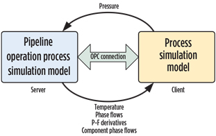
A link between the two models was established using the native pipe unit operation in the plant process simulation model, which allowed the pipeline model’s outlet stream to be connected to the plant model’s inlet stream. To establish the connection, the pipeline model was first configured to be compliant with open platform communications (OPC). Variables controlling time and speed were exposed from within the pipeline model software to start/stop the model and to allow for synchronization of simulation time (Fig. 5).2
 |
|
Fig. 5. Integrated upstream and onshore process models |
The scope of the pipeline model extended from the export of the offshore wells to the inlet of the slug catcher. Production from the wells was controlled via a source node (export) with a fixed flowrate and composition. The outlet boundary node (ending at the inlet to the slug catcher) was specified with a fixed pressure. For each case, the initial steady-state temperature, pressure, flow, compositional and phase profiles along the pipeline were configured by fixing the pressure at the outlet boundary node and running a steady-state preprocessor within the pipeline simulation software.
During transient simulations, the pressure at the outlet node was calculated by the dynamic plant model and sent back to the pipeline model as a fixed value at the beginning of each integration step. The flow conditions along the pipeline were then calculated and tracked within the pipeline simulation software, and the resulting conditions at the outlet node were sent back to the plant model. During integration, both models were executed in parallel; as a result, there was a one-step time delay when passing boundary pressure and flow information. To prevent oscillation, pressure-flow derivatives were communicated between the models to predict the boundary response during transient conditions.
Temperature and phase flow information were also retrieved by the plant model to set the composition and temperature of the inlet. For the flow ramp-up, pressure change and pigging simulation cases, a non-compositional pipeline model was used. In these cases, a fixed total composition was assumed in the pipeline model, meaning that specific component fractions were neither calculated nor tracked. For the composition change case, a separate pipeline model with composition tracking was used.
Upstream operational scenarios. Three cases were investigated as part of this analysis: pigging, flowrate ramp-up and inlet composition changes.
Pigging is a common practice in pipeline systems, wherein a pig is propelled through a pipeline by the pressure of the product flow for inspection, maintenance and cleaning. During pigging, a liquid slug is often created ahead of the pig, which can result in a sudden surge of liquid entering the slug catcher. Typically, slug catchers are designed to receive a certain net liquid volume over a specified period of time. However, if they are under-designed, the arrival of a slug can result in liquid overflow to those downstream processes where liquid could disrupt production.
For this analysis, the arrival of such a slug during pigging was simulated to determine the impact on the receiving facilities, and to verify that the sizing of the slug catcher was sufficient to receive and process the full volume of the slug.
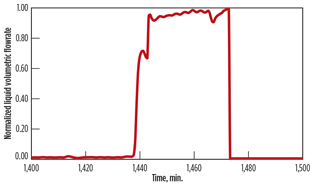
As the pig traveled through the pipeline, a liquid slug formed ahead of the pig. Fig. 6 shows the total liquid volumetric flowrate into the slug catcher. As the slug exited the pipeline, the flowrate increased and was maintained at a high rate for nearly 1 hr. The area under this curve represents the total volume of the slug.
 |
|
Fig. 6. Liquid volumetric flowrate into the slug catcher as the |
In response, flow to the condensate stabilization system was increased to maximum capacity. To analyze the capability of the stabilization system and to process the sudden increase in liquid, the relative volatility of the condensate product was tracked via the RVP. A temporary spike occurred in the RVP as the stabilizer capacity was suddenly increased. Such a disruption could have been minimized by ramping up the stabilizer capacity at a slower rate; for this case, the slug catcher would have provided a sufficient buffer volume to allow for more gradual corrective action on the stabilization system.
When the flow through a pipeline is ramped up, the increase in flowrate sweeps out the liquid within the pipeline and results in large slugs of liquid volume entering the slug catcher. To determine the impact of a ramp-up and the volumes of resulting slugs, a dynamic simulation was performed in which the inlet flowrate was increased at a predefined maximum rate from turndown conditions to the maximum production rate.
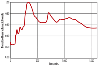
For the flowrate ramp-up case, the total mass flowrate at the inlet of the pipeline was ramped up from turndown conditions to full capacity over a period of 1 hr. Fig. 7 shows the liquid phase flowrate at the exit of the pipeline. As the flowrate increased, residual condensate built up within the pipeline was pushed out, resulting in a large surge of liquid into the slug catcher.
 |
|
Fig. 7. Liquid volumetric flowrate at the exit of the pipeline as |
For this case, the peak liquid flowrates into the slug catcher were lower than in the pigging case; therefore, flow to the stabilizer was increased more gradually. Eventually, the stabilizer reached maximum capacity well before the increase in the slug catcher liquid level subsided.
Inlet composition changes. The transition of the plant inlet composition from the pipeline was also simulated to analyze any potential operational issues. Compositional change can occur due to switching or changing of production wells with different well fluid compositions.
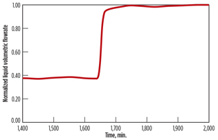
For this case, the inlet composition from the well was assumed to transition from a case with a high nitrogen content to a case with a higher concentration of heavier components, meaning more condensate formation along the pipeline. After changing the feed composition, the fraction of liquid in the feed increased as heavier hydrocarbons condensed along the pipeline.
Fig. 8 shows the volumetric flowrate of the liquid phase arrival at the inlet to the slug catcher. The wave of liquid took approximately 27 hr to traverse the entire length of the pipeline, resulting in the sudden increase shown in Fig. 8. This increase in liquid volume was found to be within the capacity of the slug catcher, and no action was required.
 |
|
Fig. 8. Liquid volumetric flowrate into the slug catcher after the |
TAKEAWAY
The impact of upstream operation on the onshore facilities can be significant and must be taken into account in design and operation. The sizing of the facility is a tradeoff between capital cost and operability. This balance can be established early in the design phase to eliminate any issues during the facility lifetime.
Analysis using an integrated model is beneficial in various ways, including for verification of the integrated operation of the entire facility. Operating procedures can be developed to handle a variety of upstream transients using these analyses and methodologies. GP
LITERATURE CITED
1Hagesaether, L., K. Lunde, F. Nygard and H. Eidsmoen, “Flow assurance modeling: Reality check and aspects of transient operations of gas/condensate pipelines,” Offshore Technology Conference, Houston, May 2006.
2Heum, J. R., “Steady state vs. dynamic simulation and OLGA,” e-Field Seminar, Dubai, UAE, November 1, 2009.
 |
Jaleel Valappil is a principal process engineer and team lead for Bechtel Oil, Gas & Chemicals’ advanced simulation group in Houston, Texas. His areas of expertise include process engineering, simulation, control and optimization. He is responsible for developing and deploying advanced technical solutions during design, commissioning and operation of various Bechtel projects, including LNG. Dr. Valappil holds a BS degree from the Indian Institute of Technology in Kharagpur, India and a PhD in chemical engineering from Lehigh University in Bethlehem, Pennsylvania.
 |
Rakesh Kumar is an engineering supervisor in Bechtel Corp.’s pipeline division. His field of experience includes process plant operation, construction, precommissioning, commissioning, detailed design and operations support for system startup. His responsibilities include flow assurance, thermal hydraulic design and assessment of gas, liquid and multiphase systems. Mr. Kumar holds a BS degree in chemical engineering from Panjab University, Chandigarh, India and an MS degree in chemical engineering from Lamar University in Beaumont, Texas.
 |
Jesse Mumm is a process engineer in Bechtel Oil, Gas & Chemicals’ advanced simulation group. His responsibilities include the hands-on development of dynamic plant models and utilizing simulation for the design, validation and optimization of LNG and gas processing plants. He holds a BS degree in chemical engineering from the University of Minnesota and has several years of experience in dynamic process simulation.


Comments