
Floating LNG's evolution from FPSO
Author: Bob Andrew, technical editor, Gas Processing
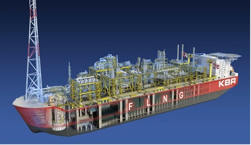
Evolution: : Floating LNG (FLNG) has always been an attractive concept for several reasons: able to be located deep offshore without requiring a jetty or product pipeline, potential to be redeployed to another large gas field, and – compared to LNG plants on land – a lesser impact on flora and fauna, indigenous peoples. Several decades of reliable track records with LNG onshore plant development and Floating Production Storage and Offloading (FPSO) gave gas field developers the confidence to now build FLNG vessels.
LNG transportation by ship began in 1959. Now over 100 LNG liquefaction trains have been constructed in 20 LNG exporting countries, and over a dozen multi-train LNG projects are under construction. FPSOs began with Shell Castillion in 1977, now there are close to 300 FPO/FPSOs deployed around the globe.
FLNG projects to date include several that are being completed and commissioned, Shell Prelude for Australia and Petronas in Malaysia. Golar have successfully converted LNG carrier vessel Hilli, with an option contract to convert the Gimi. One announced project encountered a delay, Exmar Pacific Rubiales for Columbia.
Design. In designing FLNG, consideration must be paid to topsides and ocean motion impacts. Topsides require reducing weight and footprint while accommodating ocean impacts. Added safety issues include eliminate ignition sources and cryogenic spills, reduce flammable inventories, and provide safe havens for personnel. Impacts of FLNG being in an ocean include accommodating motion modes, particularly turrets and mooring systems, and equipment internals design to control motion effects. With vapor-liquid contact devices, structured or random packing is typical, with special attention to bed height, increased liquid distribution and novel distributors. For the storage portion of the vessel, design focuses on control of sloshing.
Process. Fig. 1 is a block schematic of an FLNG processing scheme starting with feed gas to the vessel, to removal of mercury, acid gases and water, to making LNG, LPG, and stabilized condensate products. In this section we cover process options for mercury removal, acid gas removal (AGRU) and dehydration; also technology options for liquefaction.
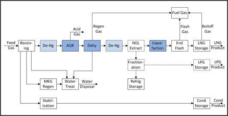
Fig. 1 FLNG process overview
Mercury is a metallurgical and personnel problem. When condensed, mercury causes embrittlement, and is typically controlled to less than 10 ng/Nm3. Fig. 2 is a generic schematic showing options where to place mercury removal within the overall process scheme. Mercury removal can be located upstream of the AGRU, which offers more protection to personnel and equipment and no dryout required. Locating it downstream of dehydration means slightly smaller beds and flexibility to use either non-regenerable technologies.
Fortunately for FLNG, there are no marinization concerns, the choice of technologies contain vapor phase and static solid phase. Choices include non-regenerable metal oxide/metal sulfide or sulfide activated carbon, or regenerable silver-doped molecular sieves. In the non-regenerable choices, the sulfide activated carbon has a lower fill cost but disposal is a concern: metal oxide/metal sulfide has lower sensitivity to liquids, and smaller bed size. Regenerable has an advantage of potential reduction in space required – integrated with mol sieve beds – and enables higher feed gas pressure to liquefaction, but the disadvantage is more complex dehydration.
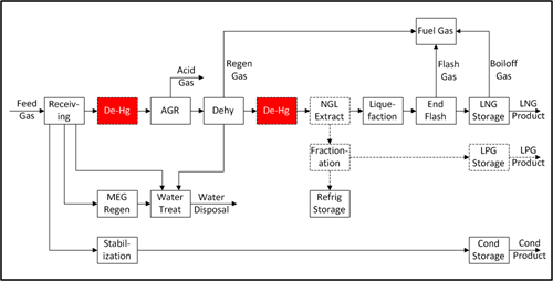
Fig. 2 Mercury removal
Acid gas specifications are driven by freezing – 50 ppmv CO2, and by product quality – 3 to 4 ppmv H2S. AGRU technologies typically use formulated MDEA or DGA in packed vapor-liquid contactors, in certain applications mol sieve or membranes are used: ocean motion impacts the separator design in all cases. Fig. 3 is a generic schematic for an acid gas removal unit. Formulated MDEA has an advantage over DGA in higher efficiency due to lower circulation/reboiler duty, lower solvent loss, less corrosion with no need of a reclaimer to dispose of heat-stable salts. It comes with a licensor guarantee of performance.
DGA is more effective at lower CO2 levels, is less impacted by low feed temperature, and no license fee. Mol sieve, although unaffected by motion, is competitive only at feed CO2 levels below 0.2%. It uses large beds with rapid cycles, has shortened bed life. CO2 is cyclically rejected to fuel gas, causing swing in Wobbe value. Membranes, also unaffected by motion, also reject CO2 to fuel gas. They are typically used for CO2 levels above 8% as pre-treat to unload the AGRU by reducing circulation and reboiler duty.
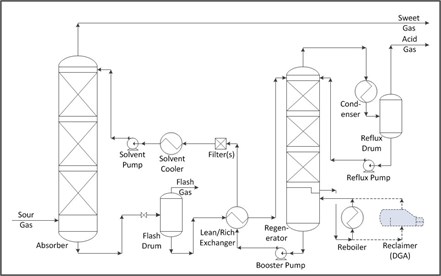
Fig 3. Acid gas removal
Molecular sieves, although unaffected by motion, are restricted to CO2 levels below 0.2%. They use large beds with rapid cycles and have shortened bed lives. CO2 is cyclically rejected to fuel gas, causing swings in Wobbe value. Membranes, also unaffected by motion, reject CO2 to fuel gas. They are typically used for CO2 levels above 8% as pretreat to unload the AGR unit by reducing circulation and reboiler duty.
Water is a freezing concern, so dehydration limit below 1 ppmv is typical. Molecular sieves are the only technology currently used, only the separators are a marinization concern. To reduce bed size, use shorter bed cycles and hotter regeneration. Spent mol sieve catalyst is not a disposal concern.
Liquefaction has a number of technology drivers. These include reducing equipment size, weight, and count, availability of refrigerant, reducing flammable inventory – especially propane, marinized drivers, source of hot utility and fuel gas integration: a dehydration / boil-off gas (BOG) variable. Shell Prelude FLNG project is one example where configuration was used to improve safety, through use of multiple decks and designing gaps between modules.
Many technologies are available from a dozen or so licensors. Not all licensors provide a performance guarantee. These technologies are dual expanders (nitrogen or natural gas), single mixed refrigerant (SMR), or dual mixed refrigerant (DMR). The use of pre-cooling, optimizing pressure, use of LNG rundown expander, cold recovery from end flash, and multiple compressor stages/casings are among the design choices to improve efficiency.
Dual nitrogen expander to date has been single train, max 1.5 MPTA. It is flexible and simpler than competing technologies, with quick response to feed changes, although less efficient. Refrigerant is inert, so not a fire hazard but is an asphyxiant. SMR has been used on LNG carrier conversions, with largest single train to date being 2 MTPA. It has lower refrigerant inventory than DMR, and there is no loss of refrigerant in the event of a trip. DMR trains for FLNG have been built over 3 MTPA and have a high efficiency, but high refrigerant inventory and storage, although propane inventory can be lower.
Mechanical drives used to date on FLNG have been aeroderivative gas turbines, electric drives and steam turbines. The gas turbines are direct mechanical drive and offer lower weight and lower system CapEx. Electric drives have higher availability, more readily configured N+1 matching driver to load, but higher system weight. Steam turbines are favored with high CO2 or high N2 in the feed gas because steam generation is able to accommodate lower LHV fuel and Wobbe Index swings, give more flexibility in matching driver to load.
Credit is given to KBR for their presentations to AIChE South Texas Section in March 2016 and Topsides Conference in February 2015 that are the basis for this article


Comments