
Optimize capacity and efficiency for an amine unit
M. Pieronek, P. Krouskop and B. Burr, Bryan Research and Engineering Inc., Bryan, Texas; and S. Kitsatienkun, PTT, plc, Rayong, Thailand
The removal of carbon dioxide (CO2) from natural gas is a necessary treating step prior to cryogenic processing. At PTT’s Gas Separation Plant No. 5 (GSP5) in Rayong, Thailand, the wellhead gas has CO2 concentrations ranging from 19 mol% to 23 mol%. This gas feeds an amine sweetening unit, where most of the CO2 is removed.
The sweet gas product is dried before entering a cryogenic demethanizer, where ethane and heavier NGL are recovered. The demethanizer overhead reaches temperatures as low as –100°C to –120°C. To prevent CO2 freeze-out, the CO2 concentration in the sweet gas must be less than 900 ppm.
This study examines the optimization of the amine sweetening unit to increase throughput, provide adequate cold protection and avoid corrosion in the amine regenerator.
Amine gas treating at PTT. CO2 is a major impurity in natural gas wells that causes corrosion in transportation pipelines and may form a solid “hydrate” in the presence of water. CO2 can also freeze by itself (forming “dry ice”) at cryogenic gas plant conditions. The required CO2 level to prevent solids formation in the cryogenic NGL recovery process is in the hundreds-of-ppm range.
In the past, primary and secondary amines were used to sweeten natural gas to low CO2 levels. Lately, methyldiethanolamine (MDEA) has become a popular solvent because it is less corrosive and needs less heat for regeneration.
However, MDEA by itself is slow to absorb CO2.1 Within typical amine absorbers, there is insufficient contact time for the gaseous CO2 to mix with the aqueous MDEA cations. Therefore, MDEA is usually incapable of sweetening gas to the ppm levels demanded by cryogenic gas processing. However, blends of MDEA with certain activating agents have been found to hasten CO2 absorption so that gas can be suitably treated for subsequent cryogenic processing. These activators are added in small amounts to the MDEA solution to enhance the CO2 absorption while mostly maintaining the desirable qualities of MDEA.2, 3 The primary reactions for an amine process are shown in Eqs. 1–3:
H2O 1 H+ + OH–(1)
CO2 + OH– 1 HCO3–(2)
MDEA + H+ 1 MDEAH+(3)
Eq. 2 represents the hydrolysis of CO2. The reactions for the activator are shown in Eqs. 4–6:4
AM + CO2 1 AM × (CO2)(4)
AM × (CO2) + H2O 1 AMH+ + HCO3–(5)
AMH+ + MDEA 1 MDEAH+ + AM(6)
where AM represents different activators available on the market, such as diglycolamine (DGA), monoethanolamine (MEA), diethanolamine (DEA) and piperazine.
The reactions show that the activator cation reacts directly and quickly with CO2. Then, another fast reaction occurs when the CO2 flips from the activator cation to the MDEA cation. This combination of two rapid reactions replaces the slow reaction sequence that occurs when CO2 is absorbed by MDEA alone. The activating agent does have its own small amount of absorption capacity, which comes with a high regeneration energy that is comparable to other primary or secondary amines.1
The activated MDEA blend’s activating energy increases proportionally to the amount of activating agent in the blend. Since the activating agent is present in small amounts, the low regeneration energy benefits of MDEA are largely achieved.
A study of PTT’s activated MDEA sweetening unit was undertaken to maximize plant throughput, minimize operating expenses, reduce corrosion and maintain adequate CO2 removal. The study was accomplished by first creating a model in a proprietary process simulation program5 and comparing it to plant operating data to ensure a good match. Then, scenarios covering several key operating parameters were run to examine alternatives and determine optimum operating conditions.
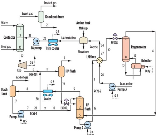
Existing plant operation. The process flow diagram for the amine sweetening unit is shown in Fig. 1. The gas plant consists of two identical amine trains. Sour gas is split equally by flow controllers to each packed bed absorber, where it contacts the amine solution. The sweet gas is then dried before entering the ethane recovery unit.
 |
|
Fig. 1. Process flow diagram for the amine sweetening unit. |
Rich amine solution leaves the absorber bottom and proceeds to a high-pressure (HP) flash tank, where most light hydrocarbons and some acid gas are flashed. The rich amine from the HP tank proceeds to a lower-pressure (LP) column, where it contacts regenerator acid gas to scrub and recover any residual amines. The rich amine is then regenerated in a hot oil reboiled stripper.
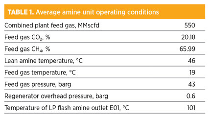
Simulator data vs. operating data. Operating data for the unit from July 1, 2014 to August 19, 2014 were used in the simulation software to calculate plant performance. The average operating conditions are shown in Table 1.
 |
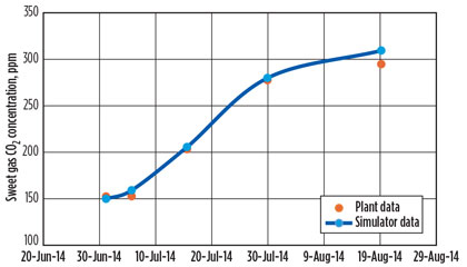
The absorber and regenerator are modeled using an electrolytic software function in the simulator. Excellent agreement between simulator predictions and plant measurements of sweet gas CO2 concentration are shown in Fig. 2.
 |
|
Fig. 2. Simulator vs. operating data for sweet gas CO2 concentration. |
Process optimization. Since the simulator accurately represents plant performance, it can be used to carry out plant optimization. During the optimization study, the desire is to most profitably utilize the process equipment without violating any of the product quality, reliability or equipment constraints. One requirement is to keep the treated gas below the 900-ppm CO2 specification while reliably operating the amine unit. Optimization will consider opportunities to reduce reboiler duty. Also, avoidance of corrosive conditions in the reboiler will be monitored within the simulation strategy.
Optimization input variables. Several adjustable input parameters (or manipulated variables) are considered in this study:
- Reboiler duty. The reboiler duty will be optimized primarily to avoid corrosion in the regenerator and ensure that constraint variables are within limits. If there is additional flexibility, reboiler duty will be reduced to save energy.
- Amine ratio. The amine ratio (mass rate of activator to mass rate of MDEA) describes the proportion of activator relative to base amine (i.e., MDEA) in the custom amine blend. Too low of a ratio may reduce the effectiveness of the solvent in absorbing CO2, while too high of a ratio will increase the required duty for regeneration. The optimization will determine the optimal amine ratio for meeting the CO2 specification at a minimum reboiler duty.
- Amine circulation rate. The circulation rate will be optimized to keep the treated gas below the CO2 specification while not exceeding a rich loading limit. Rich loading must stay below a certain limit to prevent corrosion.
- Plant throughput. Plant operating conditions are optimized at various throughputs. Usually, more gas is available than the PTT plant can process. The ultimate goal is to find the highest possible throughput for the amine unit.
Constrained variables. Optimization of the adjustable inputs is subject to the following constraints:
- Sweet gas CO2 concentration. The maximum limit for the sweet gas CO2 concentration is 900 ppm. However, a target of 300 ppm is used in the study to accommodate any sudden acid gas spikes in the feed.
- Reboiler vapor CO2 concentration. As discussed in literature, high concentrations of CO2 in the presence of water cause corrosion in the reboiler tube bundle.6 The recommended maximum CO2 concentration in the reboiler vapor is 1% when carbon steel is the material of construction for the reboiler.
- Rich loading. A maximum of 0.53 mol/mol rich loading is used to avoid corrosion.
- Lean amine pump capacity. The maximum capacity of the existing amine circulation pump is 1,200 m3/hr. The throughput optimization study considers the opportunities available if this pump capacity is increased.
- Column flood. Simulator calculations for flooding in the amine contactor are limited to 85%. The throughput study is limited to opportunities within this maximum flood limit. Major column capacity expansions are quite expensive, so it is assumed that no throughput opportunities are available that will cause flooding in the existing absorber.
- Reboiler duty. The maximum available reboiler duty is 65 MW. The throughput optimization study considers the opportunities available if the reboiler bundle and hot oil system capacities are enhanced.
Phase 1: Optimization at existing inlet gas rate. The case study aimed to establish the best operating conditions for the plant. The amine ratio and reboiler duty are varied for the existing throughput level (275 MMscfd) to determine the operating conditions with the lowest operating cost, within the plant constraints. It should be noted that, at 275 MMscfd, amine absorber and regenerator flooding are well below the limits and are omitted from the Phase 1 constraint analysis.
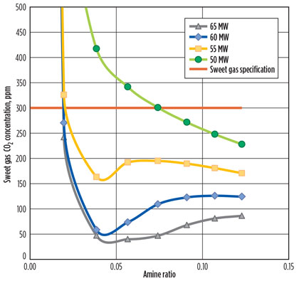
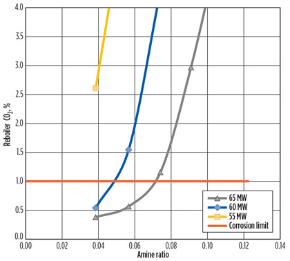
Adjusting amine ratio at reboiler duties. The amine unit reboiler was designed to operate at 60 MW and at an amine ratio of 0.12 while treating 265 MMscfd of sour gas. At present, the feedrate is 275 MMscfd, the amine ratio fluctuates from 0.04 to 0.12 due to amine makeup and losses, and the reboiler duty averages 55 MW. As discussed previously, changes in activator concentration affect both the sweet gas CO2 concentration and the required regeneration duty. Fig. 3 shows the sweet gas CO2 concentration vs. the amine ratio for several duties.
 |
|
Fig. 3. Absorber performance for various amine ratios. |
The graph shows that amine ratios below 0.04 show drastic increases in sweet gas CO2 concentration. Therefore, ratios below 0.04 will not be considered for future analysis. For the range of 0.04 to 0.12, the amine ratio does not have a major impact on the CO2 in the sweet gas, which is always well below the 300-ppm target (except for the 50-MW case). At the existing operation, the amine ratio can be reduced below the design value without detrimental effect. Fig. 3 also shows that it is possible to reduce the reboiler duty by at least 23% without going over the 300-ppm CO2 target. However, other constraints must be considered before the optimal amine ratio duty can be determined.
Optimizing reboiler duty. As previously observed, a reboiler duty above 55 MW has a relatively minor effect on the CO2 sweet gas concentration for the plant. However, to ensure reliable plant operation, a study is conducted to observe the rich amine loading and the reboiler vapor CO2 concentration at various duties to determine the minimum duty requirements. Both of these variables can lead to corrosion when they exceed their recommended limits. Fig. 4 represents the regenerator performance for various operating points discussed in Fig. 3.
 |
|
Fig. 4. Reboiler vapor CO2 concentration vs. amine ratio. |
Fig. 4 shows a drastic increase in reboiler vapor CO2 concentration as the amine ratio increases. At the maximum ratio (0.12), the CO2 concentration in the reboiler vapor is 7% for maximum capacity (65 MW). At 50 MW, the CO2 concentration in the reboiler vapor is well above 5% for a 0.04 amine ratio (not shown on the graph). Carbon steel is highly susceptible to corrosion at these conditions. Concentrations above 1% can cause corrosion issues in the reboiler, and other materials (stainless steel) is required to avoid corrosion at concentrations above 5%.
High CO2 in the reboiler vapor indicates insufficient stripping in the lower section of the regenerator, which can lead to corrosion on the reboiler tube bundle. Cavitation damage of the tubes, caused by the formation and collapse of vapor bubbles near the tube surfaces, leaves the metal susceptible to oxidation by bicarbonate in the liquid solution.7 As a result, rapid corrosion occurs in localized areas of the tube where this phase change occurs. This is known as pitting corrosion.
In the past several years, PTT has experienced leakage of hot oil into the amine solution due to tube bundle corrosion. Fig. 4 shows that over-concentration of activator drastically increases CO2 concentration in the reboiler vapor. Activators require more energy to regenerate CO2 than does MDEA. Therefore, over-concentration of activator for a system with fixed duty results in less stripping capability, which leads to corrosion issues.
Fig. 4 also shows that lowering the amine ratio reduced corrosion potential in the reboiler. The rich loadings for all amine ratios studied were below 0.53. Therefore, the optimal amine ratio for the existing plant is 0.04, as shown in Figs. 3 and 4. Due to the corrosion constraint, the minimum duty required for the amine unit is 58 MW at the optimal amine ratio. Here, the plant is able to minimize energy consumption while satisfying all constraints. Therefore, an amine ratio of 0.04 is used as the basis in the unlimited feed process optimization study.
Phase 2: Optimization with unlimited feed availability. With the acquisition of new gas sources, PTT hopes to increase the capacity of GSP5. The next optimization study relaxes the limit on the inlet gas rate, which was set to 275 MMscfd in the prior case. Again, amine circulation, amine ratio and reboiler duty are adjusted to determine optimal operating conditions.
Another factor to consider is that the amine circulation rate and reboiler duty limits could be increased through reasonable equipment upgrades. Potential gas treating capacity increases, which are subject to these equipment upgrades, are presented.
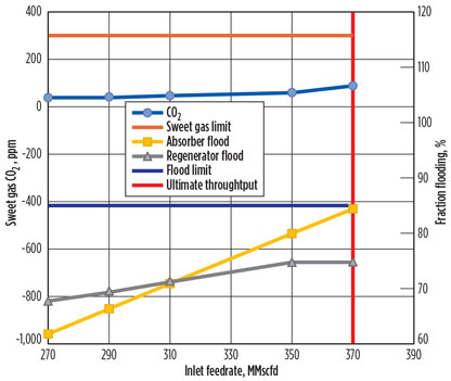
Column flood. The capacity of the contactor determines the ultimate throughput of the plant because it is prohibitively expensive to add hydraulic capacity to major distillation columns. The correct response to this problem is to build additional gas treating and processing trains. Also, absorber hydraulic capacity is largely dependent on vapor traffic. Therefore, the graph of the inlet feedrate vs. column flooding in Fig. 5 shows an ultimate throughput of 370 MMscfd at 85% flood.
 |
|
Fig. 5. Amine absorber capacity. |
This study assumes constant inlet gas and an absorber pressure of 43 barg. If the inlet gas pressure were to change, then this optimization would need to be reevaluated, as absorber flood is also a strong function of column pressure. Finally, the regenerator is well below its flood limit and is not considered to be a constraint in this study.
Note: The ultimate throughput assumes unlimited amine circulation and reboiler availability to meet previously stated plant constraints. The rest of this discussion focuses on the potential investment needed to achieve the ultimate throughput.
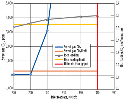
Circulation rate. Scenarios are run with various inlet gas rates from 270 MMscfd–370 MMscfd at maximum reboiler duty (65 MW) and maximum circulation rate (1,200 m3/hr). A graph of the inlet feedrate vs. sweet gas CO2 concentration and rich amine loading is shown in Fig. 6. As mentioned, the amine ratio is set to 0.04.
 |
|
Fig. 6. Absorber performance at maximum pump capacity. |
Fig. 6 shows that the sweet gas CO2 concentration increases rapidly for throughputs beyond 290 MMscfd. At 300 MMscfd, the CO2 concentration in the sweet gas is well above the 300-ppm target. An inspection of the absorber’s CO2-rich approach shows it is rich-end pinched and slips CO2 into the sweet gas, as shown by the drastic CO2 increase in Fig. 6. The sweet gas CO2 limit shows that the column can handle a maximum of 293 MMscfd. However, above 285 MMscfd, rich loading increases beyond 0.53 for a fixed amine circulation.
A side-by-side comparison of the rich loading and sweet gas CO2 limit shows the rich loading as the limiting factor when amine circulation is limited. The reboiler vapor CO2 is found to be well below 1% for all cases studied in Fig. 6. Therefore, the maximum achievable throughput with the existing pump capacity is 285 MMscfd, representing a 3.5% increase in inlet gas capacity without any equipment upgrades.
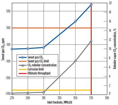
A second study is repeated with the amine circulation rate controlled in the simulation to always maintain a rich amine loading of 0.53. Cases here often exceed the previous amine rate upper limit of 1,200 m3/hr. To achieve these conditions, additional amine circulation capacity is required. A graph of inlet feedrate vs. sweet gas CO2 concentration and reboiler vapor CO2 concentration is shown in Fig. 7.
 |
|
Fig. 7. Amine absorber performance at 65 MW and 0.53 rich loading. |
Increasing the circulation rate resolves the absorber rich-end pinch issue and permits higher throughput. Fig. 7 shows the absorber and regenerator performance side by side for increasing feedrate. The absorber can accommodate 340 MMscfd without exceeding the sweet gas CO2 limit. However, above 315 MMscfd, the system exceeds its reboiler vapor CO2 concentration limit. With additional circulation capacity, the reboiler vapor CO2 becomes the limiting factor. Results from Fig. 7 indicate that investing in an additional lean amine pump can raise potential throughput to 315 MMscfd (an 8% increase from the previous maximum).
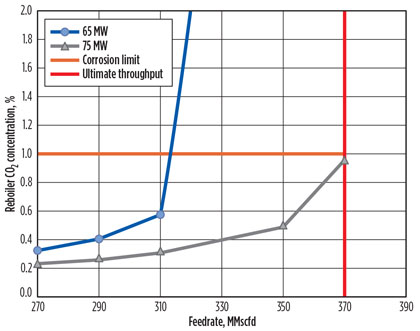
Reboiler duty. After increasing amine circulation capability, corrosion due to insufficient reboiler duty is the next limitation. In this study, the reboiler duty is increased to 75 MW. The amine circulation is controlled to meet rich loading of 0.53, and the amine ratio is set at 0.04.
Fig. 8 shows a drastic increase in the absorber performance, but only a slight increase in the regenerator vapor traffic. An additional 10 MW of duty allows the amine unit to meet its CO2 sweet gas specification at the ultimate throughput (370 MMscfd). Furthermore, the reboiler performance is drastically improved.
 |
|
Fig. 8. Amine absorber performance at 75 MW and 0.53 rich loading. |
Results from Fig. 9 show that the plant reaches maximum potential gas feed of 370 MMscfd (a 17% increase from the previous maximum), with a reboiler duty of 75 MW and an amine circulation system capacity of 1,570 m3/hr.
 |
|
Fig. 9. Effect of reboiler duty on reboiler vapor CO2 concentration. |
Optimization guidelines. The thorough investigation of plant operating parameters allowed the identification of two important bottlenecks: circulation rate and reboiler duty. Investing in additional equipment to overcome these limits substantially improves plant performance, as shown in Table 2.
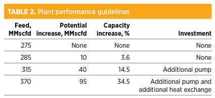 |
The existing amine unit can be optimized to achieve 285 MMscfd (a 3.6% total increase) without additional investment. Investing in an additional pump raises capacity to 315 MMscfd (a 14.5% total increase). Finally, investing in an additional reboiler allows the plant to achieve its ultimate capacity of 370 MMscfd (a 34.5% total increase).
Recommendations. In an effort to maximize plant profit, an overall analysis is performed on the gas plant’s CO2-removal unit to determine its ultimate throughput. The existing plant performance is evaluated and optimized to establish best practices at the normal gas feedrate.
Finally, amine circulation, reboiler duty and absorber hydraulic bottlenecks are studied to determine ultimate throughput conditions. A step-by-step analysis of benefits vs. each stage of investment is carried out to determine potential plant profits. A maximum increase of 35% in plant throughput can be achieved with investment in new equipment. Note: This optimization method can be applied to other gas processing plants.
Furthermore, this step-by-step approach to gas treating facility optimization is fairly simple and straightforward. Generally, when the feedrate is limited, the only optimization opportunity is energy consumption. Then, when additional inlet gas becomes available, the hydraulic limits of one of the main columns can be determined early to place an upper boundary on inlet gas capacity. After that, studies of the other manipulated variables at their initial maximum supply limits can be performed.
As each variable becomes the limiting property, its limit is relaxed to show the additional throughput opportunities available until the next manipulated variable reaches a limit. Eventually, all manipulated variables that can be upgraded at reasonable costs are studied, resulting in sets of optimum operating conditions at each manipulated variable limit.
This step-by-step optimization approach is applicable to other absorber-driven gas processing units. It can be used to determine capacity upgrade benefits, along with the corresponding equipment upgrades that may be required. GP
Literature cited
1Gas Processors Suppliers Association, GPSA Engineering Data Book, 11th Ed., 2004.
2Polasek, J. C. and G. A. Iglesias-Silva, “Using mixed amines solutions for gas sweetening,” Proceedings of the 71st Annual Gas Processors Association Convention, Tulsa, Oklahoma, 1992.
3Lallemand, F. and A. Minkkinen, “Highly sour gas processing in a more sustainable world,” Sustainable Industrial Chemistry, Wiley-VCH Verlag, Weinheim, Germany, 2009.
4Ochieng, R., A. S. Berrouk, C. J. Peters, J. Slagle, L. Lyddon and P. Krouskop, “Simulation of the Benfield HiPure process of natural gas sweetening for LNG production and evaluation of alternatives,” Bryan Research and Engineering Inc., Bryan, Texas, 2012.
5ProMax process simulator, Version 3.2, Bryan Research and Engineering Inc., Bryan, Texas, November 2014.
6Kohl, A. L. and R. Nielsen, Gas Purification, 5th Ed., Gulf Publishing Company, Houston, Texas, 1997.
7Dupart, M. S., T. R. Bacon and D. J. Edwards, “Understanding corrosion in alkanolamine gas treating plants,” Hydrocarbon Processing, April–May, 1993.
Martin Pieronek has worked as a consulting engineer at Bryan Research and Engineering (BR&E) since 2011. He oversees ProMax sales and support in the Asia-Pacific region. He also assists clients in many simulation projects, such as model verification, initial plant design, plant revamp and plant optimization. Mr. Pieronek earned his BS degree in chemical engineering at the University of California, Los Angeles and his MS degree in chemical engineering at the University of Gainesville, Florida.
Peter Krouskop started working with BR&E in 2008 as a support engineer. At present, he is the company director and a support engineer for the Malaysia office, and provides support and training to engineers in the Asia-Pacific, India and Middle East regions. Dr. Krouskop holds a BS degree in chemical engineering from the University of Houston in Texas and a PhD in chemistry from Michigan State University in East Lansing, Michigan.
Barry Burr has worked as a senior consulting engineer for BR&E in Bryan, Texas since 2007. Prior to joining BR&E, he worked as a process engineer for Koch Refining (now Flint Hills Refining) in Corpus Christi, Texas and as an advanced process control engineer for Raytheon Process Automation/Simulation Sciences, Dot Products and PAS. Dr. Burr earned his BS degree and his PhD in chemical engineering at Texas A&M University in College Station, Texas.
Sittiwat Kitsatienkun works as a process engineer at PTT’s Rayong Gas Separation Plant No. 5. He received an MS degree in chemical engineering from the Sirindhorn International Institute of Technology in Pathum Thani, Thailand and a BS degree in chemical engineering from King Mongkut’s University of Technology North Bangkok in Thailand. Apart from process engineering work, he has experience in PTT’s plant technology and innovation division, focusing on process automation and control.


Comments