
Troubleshoot and solve a gas treater downcomer unsealing problem: Part 1
H. Z. KISTER, Fluor, Aliso Viejo, California; and N. M. MOHAMED, WorleyParsons Engineering Pty Ltd., Abu Dhabi, UAE
The ADGAS Integrated Gas Development (IGD) project in Abu Dhabi transfers 900 MMscfd of dry gas from gas wells to the Habshan industrial site through a 30-in. pipeline. The project comprises a gas receiving station, three gas drying units with capacities of 300 MMscfd each, three gas turbine-driven compressors and a fuel gas treatment system with a capacity of 25 MMscfd of sweet gas.
The objective of the fuel gas treatment (FGT) is to supply sweet fuel gas for the turbines and also for the other consumers (flare purge and pilots). The FGT system consists of an absorber and a regenerator that use methyldiethanolamine (MDEA) to absorb hydrogen sulfide (H2S) out of the gas to a specification of less than 20 ppm. The system was designed by an engineering contractor from Japan, and the tower internals came from a major tray supplier.
The operational requirement of the gas turbine dictates that the fuel gas treatment unit should supply the turbine at a ramping rate of 4 MMscfd–
5 MMscfd/min for the turbine to reach the minimum governor speed. The supply should slowly increase afterward, to about 6–7 MMscfd, as the compressor/turbine picks up the feed gas load.
The FGT system was precommissioned and started up as per the instruction from the engineering contractor. When the plant was operated above 10 MMscfd, the absorber column became unstable and flooded, resulting in a sudden level rise in the fuel gas knockout (FG KO) drum, tripping the whole system. Changes to the MDEA flowrates did not appear to mitigate the situation. Attempts to raise the gas load above 10 MMscfd and keep column operations stable failed.
A thorough troubleshooting investigation by ADGAS, together with hydraulic analysis by Fluor, yielded a correct diagnosis and a successful solution. Part 1 of this article focuses on the troubleshooting investigation.
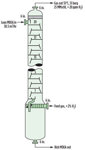
Preliminary hydraulic evaluation. The FGT absorber appears in Fig. 1. Feed gas containing less than 2% H2S enters via a vane distributor into the 1,500-mm internal-diameter bottom section. Above the vane distributor, the tower internal diameter is diminished to 1,200 mm. In the absorber, an MDEA solution contacts the gas over 20 trays to remove H2S. The gas leaving the tower has a flowrate of 25 MMscfd and contains less than 20 ppm of H2S. The MDEA design rate is 38.5 m3/hr, and it enters on the top tray. Alternative feed points permit introduction of the MDEA solution above trays 16 or 12, but, normally, neither of these trays are used.
 |
|
Fig. 1. Diagram of the FGT absorber. |
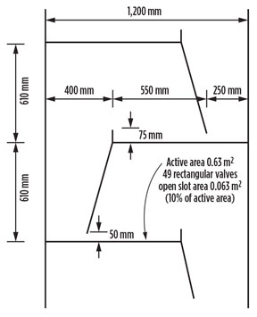
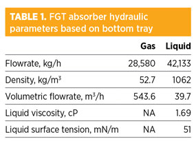
Fig. 2 shows the tray details. The trays are moving rectangular valve trays fabricated from 2-mm-thick 316L stainless steel. Table 1 shows the hydraulic design flowrates and physical properties. Table 2 shows the results of the preliminary hydraulic evaluation.
 |
|
Fig. 2. FGT absorber tray details. |
Tables 1 and 2 do not reveal anything unusual. Table 2 shows that the design point does not appear to be close to any conceived capacity limits. Calculated values by the tray supplier and Fluor were in agreement.
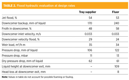
Amine absorbers are known to be foaming systems. Perry’s Chemical Engineer’s Handbook recommends the use of a derating (“system”) factor of between 0.73 and 0.8 for such systems. Indeed, the designers applied an even more conservative system factor of 0.7 in the design. The calculated percent flood values listed in Table 2 can be divided by the derating factor of 0.7 and would still maintain a comfortable margin from flood. The downcomer inlet velocity is also well below the value recommended for a foaming system.
The only parameter that appears out of range for good design practices is the head loss under the downcomer. Most designers use a value of 15 mm to 30 mm of liquid. The number calculated here is about half of the lower value, or approximately 8 mm. It results from a downcomer clearance that is larger than needed for handling the liquid flowrate. This head loss was not shown on the supplier calculation list.
Normally, this low value will not cause any problems because the downcomer will be sealed by the outlet weir. In this case, too, the outlet weir of 75 mm was tall enough to give a static seal to the 50-mm downcomer clearance. However, in this case, it became a major issue.
Initial trials and fix attempt. The tower was commissioned and operated at the MDEA solution design liquid rate of 38 m3/hr, and the gas flowrate was raised to 10 MMscfd. At approximately 10 MMscfd, the column differential pressure rose from 150 mbar to 450 mbar. Liquid carried over from the top of the absorber caused a high level in the FG KO drum downstream. This high level resulted in a system trip.
Several other trials were conducted over a period of two weeks without success. ADGAS engineers suspected a foaming problem or a major mechanical integrity incident that may have happened during commissioning. The FGT absorber was shut down, opened and thoroughly inspected, but neither mechanical damage nor fouling was found. The column was then returned to operation.
To test the foaming theory, ADGAS circulated water instead of MDEA in the absorber. The disappearance of the problem in the water test would verify foaming, while persistence of the problem in the water test would disprove foaming.
The water circulation started at a rate of 10 m3/hr and was raised in steps to 20 m3/hr. The gas rate was first raised from 5 MMscfd to 10 MMscfd. However, at 12 MMscfd, the column differential pressure increased sharply to 245 mbar, with water carryover from the top of the absorber and a high level in the FG KO drum downstream. This trial proved that a foaming problem did not exist.
Additional trials were conducted after replacing water with MDEA. Gas and MDEA flowrates were varied, and the MDEA feedpoint was changed between trays 12, 16 and 20. The tower could not achieve stable operation above a gas flowrate of 12 MMscfd. The liquid rate did not affect the tower operation.
The tray supplier and engineering contractor conducted many additional trials and performed calculations. They concluded that the sudden increase in pressure drop was due to flooding of the trays. To fix the problem, they recommended the following changes to the trays:
- Reduce the weir heights from 75 mm to 62 mm to decrease tray pressure drops and help open the valves (due to the shorter liquid head on the tray).
- Weld open all valve caps on trays 1 and 2 to prevent flood initiation at these trays.
- Replace the 4-in. drain pipe from the bottom seal pan with a 6-in. pipe. A seal cup was installed at the bottom of this pipe, which was previously unsealed. Also, a vortex breaker was added where the new pipe exited the seal pan of tray 1.
The tower was thoroughly inspected upon shutdown to perform these modifications. The tower was found to be clean, with no mechanical damage. All tray and downcomer dimensions were checked and found to be in accordance with the drawings, eliminating any possible installation errors.
Upon the tower’s return to service, only a minor improvement in operation was observed. The tower could stably operate at less than 11 MMscfd to 12 MMscfd of sour gas, and with a maximum MDEA circulation of 20 m3/hr.
In search of the root cause. Many of the troubleshooting endeavors were performed before the initial fix attempt. Several theories were proposed by the tray supplier and engineering contractor, but none were supported by the trials. Some of the key theories are outlined in the following sections.
Fouling. This is a common issue in many amine systems, mostly monoethanolamine and, to a lesser extent, MDEA. However, the inspection during the two shutdowns found the trays shining clean. The tower was water-washed before the inspection, but, even after a wash, some deposits usually remain. No such deposits were found, which conclusively denied the presence of fouling.
Damage or installation error. These theories were also denied when the tower inspection showed no damage and no installation error.
Foaming. This theory was conclusively denied when trials using water instead of MDEA showed an identical tower limitation. This testing is novel. While amine systems may foam, a gas-water system is non-foaming. Therefore, testing a foaming system using clean water instead of the potentially foaming process liquid can conclusively confirm or deny foaming.
In another test, antifoam was injected at different concentrations and different rates. Antifoam injection gave no improvement to the system performance, again denying the presence of foaming.
Hydraulic analysis (Table 2) showed that, even if foaming occurred, the tray design would handle the full design rates without flooding. In contrast, field observations showed that the column was flooding at about 40%–50% of the design rates for both gas and liquid.
High liquid level in the tower base. This is a common cause of flooding.However, the bottom of the vane vapor distributor is 1.7 m above the high-high liquid level. In some of the trials, the liquid level was lowered, but this made no difference to the amount of gas that the tower could handle. This effectively denied the high-liquid-level theory.
With all of the above theories denied, there was no explanation for the premature flood.
Second fix attempt. ADGAS has another absorber in similar service that works well. This tower contains bubble cap trays and shows no limitation with ramping up or down with gas turbine requirements. In the absence of a definition of the root cause of the problem, and in view of the tray supplier’s recommendation that valve trays should not be ramped up more than 0.5 MMscfd every 10 min (which does not fit with gas turbine fuel gas supply demand), ADGAS decided to scale up the design of the working absorber as the second fix to the absorber that was experiencing problems. Several changes were made:
- Valve trays changed to bubble cap trays
- Weir heights further reduced from 62 mm to 55 mm
- Downcomer clearances decreased from 50 mm to 40 mm
- Downcomers changed from a sloped design, with top and bottom widths of 400 mm and 250 mm, respectively, to a vertical design with a 250-mm width, which increased the tray active areas
- Open area increased from 10.3% of the active area in the valve trays to 15.6% of the active area in the bubble caps.
To avoid another failure, ADGAS asked Fluor to review the design of the second fix and evaluate whether it would solve the problem. The approach involved Fluor and ADGAS working together to identify the root cause before evaluating the solution.
Reanalysis of pressure drop data. The test and trial data (Table 3) obtained by ADGAS were jointly reviewed. The erratic nature of the pressure drop per tray obtained from the measurements is astounding. At a gas rate of 5 MMscfd, the pressure drop per tray varied from 2 mbar to 8.5 mbar per tray. At and above 10-MMscfd gas flowrates, the pressure drop varied between 8 mbar and 24 mbar per tray.
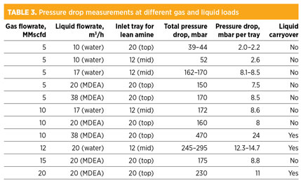
The design pressure drop for the trays in the absorber is approximately 11 mbar to 13 mbar per tray (Table 2). Since the tower operated at lower vapor and liquid loads at the trials, a 7 mbar to 9 mbar per tray pressure drop would be reasonable and would indicate good operation. High pressure drop of twice the design would indicate flooding, as previously identified.
The significant measurements appeared at the low end. At a gas flowrate of 5 MMscfd and liquid flowrates of 10 m3/hr and less, the pressure drop was small, at approximately 2 mbar to 3 mbar. When the liquid load increased from 10 m3/hr to 17 m3/hr, the pressure drop almost quadrupled to 8 mbar. This sudden change can only be explained by the downcomers completely losing their seals at the lower liquid flowrate. This issue, together with the earlier observation of a low head loss at the downcomer exit (Table 2), prompted an investigation into a downcomer unsealing problem, which, until that time, was not on the troubleshooting checklist.
Next issue. An exploration of downcomer sealing as the root cause requires a hydraulic analysis, which will be described in Part 2. GP
Note
This article will be presented at the Distillation Topical Conference of the AIChE Spring Meeting in Austin, Texas in April 2015.
 |
Henry Z. Kister is a Fluor Corp. senior fellow and director of fractionation technology. He has over 30 years of experience in design, troubleshooting, revamping, field consulting, control and startup of fractionation processes. He is the author of three books, the distillation equipment chapter in Perry’s Chemical Engineers’ Handbook, and approximately 100 articles. He has taught the IChemE-sponsored “Practical Distillation Technology” course over 450 times in 25 countries. A recipient of several awards, Mr. Kister obtained his BE and ME degrees from the University of New South Wales in Australia. He is a fellow of IChemE and AIChE and a member of the NAE.
 |
Nashaat M. Mohamed is a senior engineer for Worley Parsons Engineering–Abu Dhabi and has served as the project management consultant for ADGAS’ Offshore Associated Gas and Integrated Gas Development projects since 2008. Mr. Mohamed joined Suez Oil Processing Co. in 1971 as a process engineer. He then worked for ARAMCO from 1979, and also ADGAS between 1981 and 2008, when he retired as process team leader. He holds a BSc degree in chemical engineering from Cairo University in Egypt.


Comments