
Consider technology implications for small-scale Fischer-Tropsch GTL
A. de Klerk, Department of Chemical and Materials Engineering,
University of Alberta, Edmonton, Alberta, Canada
Small-scale GTL processes aim to produce transportable liquid products from smaller natural gas reservoirs that cannot be profitably connected to pipeline infrastructure. The size of small scale GTL processes is a byproduct of the nature of such natural gas reservoirs. There is no specific size limit beyond which GTL processes should no longer be considered as small-scale. Rather, it is contended that the design of small-scale GTL processes should be inherently different from that of large-scale GTL processes.
Smaller natural gas reservoirs unconnected to pipeline infrastructure have some characteristics that must be considered when selecting a small-scale GTL technology:
- Remoteness. When connection to pipeline infrastructure is unprofitable, it implies that the reservoir is remote with respect to the main utility grid. Access to basic utilities such as water, electricity and sewage disposal is likely to be limited.
- Accessibility limitations. The roads leading to the reservoir will have a more limited carrying capacity for heavy loads, which limits the size and weight of prefabricated equipment that can be transported.
- Transience. The productive lifetime of the reservoir will, in many cases, be limited. The first implication is that the GTL facility must be easily relocateable so that the service lifetime of the GTL facility is decoupled from the lifetime of the reservoir. The second implication is that site remediation must be easy and inexpensive.
- Location. The actual location of the reservoir matters. The climate, seasonal variability, access to skilled labor and legislation are a few of the factors that will affect the design and operability of the facility.
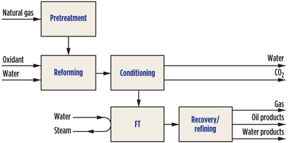
The design of small-scale GTL processes is still in the development phase. The challenge for new entrants into the field of GTL is the steep technological learning curve. The individual technologies that comprise a GTL process (Fig. 1) are licensable. The remaining challenge lies in the efficient integration of these technologies to produce a small-scale GTL process. At each step of the integration, the technology selection has implications, some of which are not immediately apparent.
 |
|
Fig. 1. Generic FT-based GTL process. |
The purpose of the subsequent discussion is to provide some insight into the implications of technology decisions. The discussion will be limited to Fischer-Tropsch (FT)-based GTL, although many of the points are equally applicable to methanol-synthesis-based GTL.
Gas pretreatment
The first step in any GTL process is gas pretreatment. The purpose of gas pretreatment is to make the gas suitable for the downstream processes. There are two groups of compounds that are usually present in natural gas and that should be removed during pretreatment—the associate NGL and the sulfur-containing compounds. Some natural gas reservoirs may also have other trace components that must be removed, but these are not discussed here.
Associated NGL. The reasons for recovering the associated NGL are twofold. First, since the objective of the process is to produce liquid products from natural gas, products that are already in liquid form should be recovered. Second, the design of the natural gas reformer depends on the gas composition. Hydrocarbons heavier than methane are more easily converted and are more prone to carbon formation under some reforming conditions. By recovering the associated NGL, the natural gas is less prone to carbon formation.
The recovery of NGL is a physical separation. The technology selection must be tailored to the reservoir characteristics. The efficiency of liquid recovery is dependent on the technology selection, and the downstream impact is localized to the gas reformer.
Desulfurization of natural gas. In large-scale GTL facilities, desulfurization is typically performed by passing the natural gas with a co-feed of hydrogen (H2) over a hydrotreating catalyst, followed by desulfurization over a packed bed of porous copper-containing zinc oxide (ZnO). The initial hydrotreating step is necessary to convert sulfur in mercaptan (thiol) and sulfide (thioether) compounds to hydrogen sulfide (H2S). The ZnO reacts with H2S to capture the sulfur as zinc sulfide (ZnS), and the packed bed is typically operated at 350°C–400°C. Once the packed bed reaches capacity, the ZnS can be regenerated by controlled oxidation. It is, therefore, customary to apply two packed beds in parallel.
Selecting ZnO-based desulfurization technology for small-scale GTL has some implications:
- •A source of pure H2 is required as utility. The issue is not H2 availability, but rather the need to include an H2 purification unit, or an external source of pure H2 in the design.
- During regeneration, a sulfur-dioxide-(SO2)-rich offgas is produced as effluent. Depending on the location, the offgas can be disposed of through a stack, or it can require gas treatment before release.
Other gas treatment strategies will have different requirements and implications. For example, spent FT catalyst makes a good sulfur trap. Gas treatment and spent FT catalyst disposal can be integrated, instead of using ZnO.
Natural gas reforming
The purpose of the natural gas reformer is to produce syngas (H2 and CO) as feed for the FT synthesis, which converts the syngas into heavier products. The flow of syngas through the GTL facility, which passes from one unit to another and may include one or more recycle streams, is called the gas loop. The gas loop design is central to the overall GTL process, and the reforming technology selection has a tremendous impact on the gas loop design.
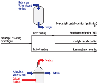
The selection of a specific reforming technology determines the importance and the impact on the gas loop of methane (CH4) conversion, the nature of the oxidant, syngas composition, and operating pressure. Before delving into the details of each, it is worthwhile to examine the technology options for natural gas reforming (Fig. 2).
 |
|
Fig. 2. Classification of natural gas reforming technologies. |
The steam reforming reaction (Eq. 1) is very endothermic (ΔHr,298 K = 206 kJ/mol), and it requires significant energy input to proceed:
CH4 + H2O r CO + 3 H2(1)
The energy to drive this reaction can be provided in two ways: directly, as part of the conversion process, or indirectly, through a utility stream. When the energy is provided directly, the oxidant is introduced into the process stream, and part of the natural gas feed is oxidized to provide energy for the steam reforming reaction.
The oxidant is, therefore, a process feed, and it enters the gas loop. The advantage of doing so is that the reformer becomes more compact in design. When the energy is provided indirectly, as a utility, no oxidant is introduced into the process stream and the oxidant does not enter the gas loop. Steam reformers tend to be bulky in design, but the advantage of keeping the oxidant separate from the process will become evident during the subsequent discussion.
Another important reaction in natural gas reforming is the water-gas shift reaction (Eq. 2), which governs the equilibrium composition of the syngas:
CO + H2O i CO2 + H2(2)
The reforming temperature affects this equilibrium, with lower temperatures favoring the production of H2. The reforming temperature, in combination with the reforming catalyst (if used), determines the reaction rates in Eqs. 1 and 2, which, in turn, affects the extent of CH4 conversion and the approach to water-gas shift equilibrium.
Methane conversion. Unconverted methane will remain in the syngas as an inert. Unless the gas loop is designed with a recycle of gas from the recovery section back to the reformer (recycle not shown in Fig. 1), any methane that is not converted during reforming remains methane. The methane then becomes part of the gas product. The gas product is, at best, a low-quality fuel gas and it is a much lower-quality fuel than the natural gas feed. The gas product has a lower quality, because the non-combustible inerts that entered the process concentrate in this stream. For example, if the natural gas contained some N2, that N2 will end up at higher concentrations in the gas product and thereby reduce the calorific value of the gas product.
Oxidant selection. Oxidant selection is critically important if the reforming technology uses direct heating (Fig. 2), because the oxidant becomes a process feed and it is no longer a utility stream. The trade-offs are complex:
- Pure O2. When pure O2 is used as an oxidant, the least amount of inert material will be introduced with the O2 into the process. The main contaminant introduced with O2 is usually argon. In large-scale GTL facilities, pure O2 is invariably used. However, it either requires the availability of an onsite air separation unit, or the continual purchase of liquid O2 as process feed. Considering the characteristics of small-scale GTL, neither of these options are attractive prospects, despite the obvious process advantage of employing pure O2.
- Air. When air is used as an oxidation agent, a large volume of inert material is introduced into the process. Although the inert material does not participate in the downstream conversion, it affects the process design in three ways. First, it reduces the concentration of the reactive components, which causes a decrease in the rate of reaction during reforming and FT synthesis, which makes separation less efficient. Second, it increases the size of all equipment and piping, because the gas volume is increased by the inert components in the gas. Third, it necessitates an open gas loop design—i.e., no recycle of gas back to the reformer. For the most part, the implications of using air as an oxidant are negative. Yet, there may be pragmatic reasons for using air in a small-scale facility to avoid the complexity associated with the use of pure O2.
Operating pressure. Most large-scale GTL facilities operate with a gas loop pressure in the range of 1.9 MPa–2.5 MPa (275 psi–360 psi). FT synthesis can be conducted at near-atmospheric pressure, but the reaction rate increases and the equipment size decreases as the operating pressure is increased. There are also costs involved with operating at higher pressure. Any operating pressure above the production pressure of the natural gas from the reservoir requires additional gas compression. Furthermore, when the reforming technology involves direct heating (Fig. 2), the pressure of the oxidant co-feed must also be increased.
Compressors are expensive capital equipment that are costly to operate and that have a large utility footprint. The operating pressure of the gas loop, in conjunction with the technology selection for gas reforming, determines the compressor requirements. The reliability of the compressor type and the utility requirements associated with the compression needed to achieve the operating pressure must be carefully considered in relation to the location of the small-scale GTL facility.
Syngas composition. The syngas composition produced by the natural gas reformer largely depends on the technology selected in combination with the feed gas composition. What is of importance to the downstream process is the H2:CO ratio in the syngas. If the H2:CO ratio does not match the downstream process requirements, then the H2:CO ratio will have to be changed during syngas conditioning. The H2:CO ratio increases with decreasing outlet temperature and increasing steam-to-carbon ratio in the feed to the natural gas reformer: non-catalytic partial oxidation (approximately 1–2) < autothermal reforming (approximately 2–4) < steam methane reforming (approximately 3–5).
Syngas conditioning. The syngas produced by natural gas reforming is also called “raw gas” to differentiate it from the conditioned syngas feed used for FT synthesis. Syngas conditioning involves one or more of the following three steps:
- Condensation and recovery of water from the raw gas
- Separation and recovery of some or most of the CO2 from the raw gas
- Water-gas shift conversion of the raw gas to manipulate the H2:CO ratio of the raw gas.
Of these processing steps, only the condensation and recovery of water are always necessary, as well as beneficial. The removal of CO2 and manipulation of the H2:CO ratio depends on the requirements imposed by the gas loop design and the technology selected for FT synthesis.
Fischer-Tropsch synthesis
FT synthesis is the process step that is responsible for converting the syngas into heavier products. The product obtained from FT synthesis is a mixture of hydrocarbons, oxygenates and water. The three most common organic compound classes that are produced are paraffins (Eq. 3), olefins (Eq. 4) and alcohols (Eq. 5):
n CO + (2n + 1) H2 r CnH2n + 2 + n H2O(3)
n CO + 2n H2 r CnH2n +n H2O(4)
n CO + 2n H2 r CnH2n + 1OH + (n – 1) H2O(5)
Other organic compound classes can also be formed, such as carbonyls (aldehydes and ketones), carboxylic acids and aromatics.
The carbon chain length, n, follows a fixed distribution, which is called the Anderson-Schulz-Flory (ASF) distribution. The ASF distribution is a consequence of the way in which the products are formed on the FT catalyst. For every step of the reaction, there is a chance that the molecule being synthesized will either increase in length by one carbon, or leave the catalyst as a final product.
The probability that the molecule will increase in length is expressed in terms of a single variable, α, called the alpha-value. The alpha-value is determined by both the FT catalyst and the operating conditions. The mole fraction of compounds with (n + 1) carbons will be related to the mole fraction of compounds with n-carbons by Eq. 6:
xn + 1 / xn = α (6)
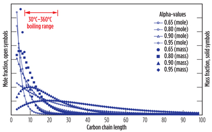
Using the relationship shown in Eq. 6, it is possible to calculate the ASF product distribution that will be obtained from FT synthesis with a known alpha value. The impact of choosing different alpha values on the resulting product distributions is illustrated in Fig. 3. The only two carbon numbers that do not follow this relationship are C1 and C2. Normally, the C1 mole fraction is higher than predicted from Eq. 6, and the C2 mole fraction is lower than predicted from Eq. 6. The values for C1 and C2 compounds are, consequently, not shown in Fig. 3. Other subtleties affect the product distribution, as well, but the ASF distribution is usually a good approximation of the carbon distribution that is obtained during industrial operation.
 |
|
Fig. 3. Mole fraction and mass fraction distribution of different alpha-value |
The selection of the FT technology holds implications for the upstream and downstream design of the GTL process. These implications will be discussed in terms of the key parameters that can vary. Note: It is possible to create “new” FT technologies by combining these parameters into different groupings. This is one of the main advantages of FT synthesis, because it provides the design engineer with ways to manipulate the nature of the product to best fit the application. It is unfortunate that the technology selection for recent industrial GTL facilities has created a more monochromatic impression of what is desirable and what is not.
FT alpha-value. The alpha-value cannot be selected independently of the FT catalyst type, reactor type and operating conditions. Nevertheless, it is advisable to estimate what alpha-value best suits the design intent of the small-scale GTL facility. The alpha-values of industrial GTL processes are in the range of 0.60–0.95.
A high alpha-value limits the production of normally gaseous lighter products while producing a broad distribution of products (Fig. 3), including a significant fraction of waxes. A low alpha-value produces a significant fraction of lighter products, including naphtha and normally gaseous products, but the boiling range distribution is narrow, and almost no heavier products are produced (Fig. 3).
In a small-scale GTL facility, gaseous light products and waxes are usually undesirable products. The following implications should be considered:
- Normally gaseous light products (C1–C4). Just like the natural gas feed, the problem with the normally gaseous products that are produced by FT synthesis is transportability to the market. The olefinic C2–C4 gases can be converted into liquid products using oligomerization technology. For example, high conversion of light olefins to naphtha and kerosine boiling-range products is possible over a solid phosphoric acid catalyst. The paraffinic C1–C4 gases are inert to this type of conversion. Although some of the light gases will also dissolve in the oil product, most of the light paraffinic gases are undesirable FT products in a small-scale GTL facility. In this context, the light paraffinic gases effectively have the same value as the natural gas feed at that location, because the gaseous products cannot be brought to market.
- Waxes. In large-scale GTL facilities, waxes are desired products. In small-scale facilities, the presence of waxes creates a challenge in terms of production, conversion and marketing. Heavy waxes readily congeal in cold spots, and all process equipment in contact with waxes must be rigorously heat-traced. To convert waxes into liquid oil products, a hydrocracker is needed. Hydrocracking technology requires high-pressure purified H2 and a fired preheater, which are both onerous requirements in a small-scale GTL facility. Alternatively, the waxes can be recovered as a slack-wax product that can be marketed separately from the oil product.
FT catalyst type. All industrially used FT catalysts are based on either iron (Fe-FT) or cobalt (Co-FT). The selection of one catalyst type over the other is a process-specific selection that is based on the different characteristics of the catalysts (Table 1). The comparison assumes that the Fe-FT and Co-FT catalysts are both state-of-the-art, industrially produced catalysts that are skillfully operated. The implications of the catalyst selection for the process follow from the catalyst characteristics.
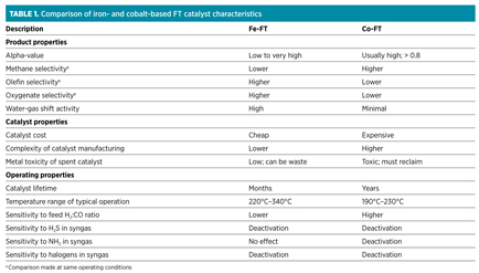
Many of the characteristics stem from the hydrogenation activity of the two metals. The hydrogenation activity of iron is lower than that of cobalt. The main advantage of lower hydrogenation activity is that Fe-FT catalysts can be operated over a much wider temperature range than can Co-FT catalysts. At higher operating temperatures, Co-FT catalysts become strong methanation catalysts. The main disadvantage of lower hydrogenation activity is that the product from Fe-FT synthesis contains more oxygenates.
In addition to the implications that stem from the characteristics of the two catalyst types shown in Table 1, there are two issues of common misconception:
- CO2 footprint of Fe-FT vs. Co-FT. The net CO2 footprint of an FT-based GTL process is determined by the reaction stoichiometry and energy requirements of the process. The stoichiometry of FT synthesis, shown in Eqs. 3–5, is similar for Fe-FT and Co-FT catalysts. The main difference between Fe-FT and Co-FT is the step in the process where most of the water-gas shift conversion (Eq. 2) takes place. In the case of Fe-FT, water-gas shift conversion takes place in parallel with FT synthesis, but this does not mean that Fe-FT has a larger CO2 footprint than does Co-FT. The overall CO2 footprints for Fe-FT- and Co-FT-based GTL processes are similar.
- Fe-FT catalyst lifetime. The reported catalyst lifetimes for Fe-FT catalysts span a wide range. The catalyst lifetime is based partly on the operating temperature, as well as on minimum acceptable activity and alpha-value. At operating temperatures typical of high-temperature FT synthesis processes (typically > 320°C), catalyst lifetime is mainly determined by activity loss. However, at lower operating temperatures, which are more typical of low-temperature FT synthesis, acceptable activity can be maintained for much longer, but at the expense of a slight decrease in alpha-value (i.e., lower wax selectivity) and an increase in olefin content of the product. For small-scale GTL applications that aim to produce oil or fuels, catalyst lifetimes in the order of a year—and possibly longer—can be anticipated.
FT operating conditions. The operating temperature is the most important of the operating conditions to select. The selectivity profile of FT synthesis is sensitive to the operating temperature, especially for Co-FT, which has a narrow operating window compared to Fe-FT (Table 1). An increase in operating temperature leads to a decrease in alpha-value. The implications associated with changes in the alpha-value have already been discussed. Generally speaking, higher operating temperature disqualifies Co-FT and places more emphasis on the need for an oligomerization process downstream from FT synthesis.
Another important aspect of the operating temperature is the quality of the steam that is generated by removal of reaction heat during FT synthesis. FT synthesis is very exothermic; about 20% of the calorific value of the methane feed is released during the FT reaction. This makes the steam production during FT synthesis a meaningful energy flow in relation to the overall GTL process. The higher the operating temperature, the higher the steam temperature and pressure, which makes the steam more useful. The importance of producing high-quality steam in a small-scale GTL facility depends on the design of the GTL facility and its location.
Operating pressure affects the alpha-value and volumetric reactor productivity. The pressure will likely be determined by the technology selection for gas reforming.
The syngas composition is important, and it is affected by the design of the FT gas loop. When the gas loop includes one or more syngas recycle streams, the H2:CO ratio produced by the reformer is less critical.
Generally speaking, the FT synthesis becomes more sensitive to the H2:CO ratio of the syngas feed at higher per-pass conversion in the reactor. The increased sensitivity to the H2:CO ratio at high conversion is because H2 and CO are consumed in a specific ratio (Eqs. 3–5). Co-FT is more sensitive to the H2:CO ratio of the feed. Fe-FT is water-gas shift-active and will tend to produce a more H2-rich syngas due to the water-gas shift equilibrium (Eq. 2) at low temperature that favors H2 over CO.
FT reactor type. The reactor type must be selected in combination with the nature of the catalyst and operating conditions. Heat management is central to the design of reactors for FT synthesis. Although near-isothermal operation is preferable, it is important to understand the origin of this requirement.
Activity and selectivity during FT synthesis is sensitive to temperature. If waxes are the preferred products (as is often the case in large-scale, low-temperature FT GTL facilities), then any localized temperature increase results in a loss of wax selectivity. In small-scale GTL facilities that aim to produce oil, the stringency of this requirement can be relaxed for Fe-FT and, to a lesser extent, for Co-FT, due to its narrower operating window (Table 1). Depending on the extent of the deviation from isothermal operation, there is a risk that methane selectivity will be increased, or that catalyst deactivation will be increased. These are general reaction-engineering concerns and are not just specific to FT synthesis.
The process implications for the main reactor types employed in FT synthesis are:
- Fixed-bed. Multitubular or microchannel fixed-bed reactors approach ideal plug-flow reactor behavior. The main advantages for small-scale GTL facilities are their robustness of operation and the localized deactivation of catalyst when there are impurities in the syngas. The main disadvantages are the need for manual loading/unloading and the inability to replace catalyst while onstream. Size and cost can be minor disadvantages.
- Slurry bubble column. Slurry bubble column reactors can only be used when the alpha-value of FT synthesis is high enough so that there is a liquid phase present at synthesis conditions. Slurry bubble column reactors have behavior that can be approximated by one to three continuous stirred tank reactors in series. The main advantages are high heat transfer for near-isothermal operation and the ability to add and remove catalyst while onstream. The main disadvantages are difficult catalyst/product separation and bulk poisoning of the catalyst when there are impurities in the syngas.
- Fluidized bed. Fluidized-bed reactors can only be used when the alpha-value of FT synthesis is low enough so that there is a no-liquid phase present at synthesis conditions. Therefore, this reactor type is found only with high-temperature FT synthesis using Fe-FT catalysts. The main advantages are simplicity of construction (fixed-fluidized bed) and the ability to add and remove catalyst while onstream. The main disadvantage is bulk poisoning of the catalyst when there are impurities in the syngas.
Product recovery
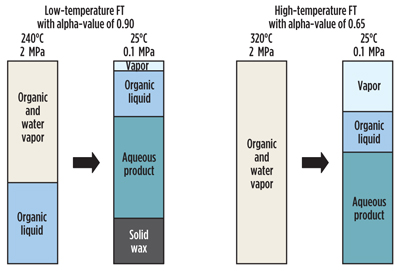
The product from FT synthesis at ambient conditions consists of gaseous compounds, an organic oil phase, a solid wax phase (when the alpha-value is high) and an aqueous phase that contains dissolved short-chain oxygenates (Fig. 4). The relative amounts and the composition of each product phase depend on the nature of the FT synthesis and the conditions of product recovery. The product from FT synthesis is not a single-phase hydrocarbon oil, and although product recovery seems like a simple matter of condensation and phase separation, the vapor-liquid-liquid equilibrium is complex.
 |
|
Fig. 4. Product phases during FT synthesis and at ambient conditions. Inert |
The nature of the product separation associated with the product recovery affects the downstream design and the efficiency of the FT gas loop. The impact of poor product recovery design on downstream operation should not be underestimated and is not necessarily apparent from calculations. For example, if the design does not allow complete recovery of short-chain carboxylic acids in the aqueous product, then the oil phase will become corrosive, affecting the material selection of downstream equipment. The composition of the different product fractions produced during product recovery also affects the efficiency of product refining units.
Product refining. The extent of refining that is required in small-scale GTL facilities depends on two decisions, both of which affect the economics of the overall process. First, there is the nature of the products that must be produced for the intended market, which is a business decision. Second, there is the refining units needed to convert light gaseous hydrocarbons and/or solid slack waxes into liquid products, which are needed to improve the overall liquid yield of the GTL facility.
The incremental cost associated with FT refining can usually be economically justified by the increased value of the refined products. However, the primary aim of small-scale GTL is to produce a transportable product. Value addition to the transportable liquid product can take place in a centralized, larger-scale facility, and it does not need to be part of the small-scale GTL facility. Generally, two refining units should be considered for possible inclusion in a small-scale GTL design: olefin oligomerization and wax hydrocracking. The relative need and importance of each is a consequence of the FT technology selection and, in particular, the alpha-value of FT synthesis.
Olefin oligomerization. The importance of olefin oligomerization in a small-scale GTL facility increases as the fraction of light olefins in the FT product increases. By not including an olefin oligomerization unit, much of the light olefins will remain as vapor-phase product with the same lack of transportability as the natural gas feed.
There are many olefin dimerization and oligomerization technologies from which to choose. Most technologies are based on the use of an acid catalyst in a fixed-bed reactor. Oligomerization proceeds by successive dimerization reactions (Eq. 7):
2 CnH2n r C2nH4n(7)
Luckily, most olefin oligomerization technologies are fairly robust and well suited for small-scale implementation. In the context of a small-scale GTL facility, it is preferable to select an oligomerization technology that has the following characteristics:
- Feed flexible. It is necessary for the oligomerization process to be effective with a range of feed compositions. The implication of selecting a technology with limited feed flexibility is that changes in the alpha-value of the FT catalyst will hamper the efficiency of light olefin recovery.
- Moderate operating temperature. The oligomerization process should not require feed preheating beyond a temperature that can be provided by the steam generated from cooling the FT reactor. Furthermore, oligomerization is thermodynamically favored by low temperature. The implication of selecting a technology with more onerous preheating requirements is that a fired heater will be required. Fired heaters are both expensive and bulky.
- High selectivity to heavy naphtha and distillate. The objective is to recover the light olefins by converting them into liquid products. Ideally, most of the olefinic product should be heavy enough to be easily recoverable by condensation. The implication of selecting a technology that favors dimerization is that some products will be in the light naphtha range, which is more difficult to recover.
- High once-through liquid yield. The olefin oligomerization technology must be able to convert the olefins efficiently, even at low olefin partial pressure in the gaseous feed. The implication of poor conversion at low olefin partial pressure is a decrease in overall process efficiency and profitability.
- Product quality. Depending on the intended market, some olefin oligomerization processes may produce better-quality products that can be sold as blending components. Although this will increase the logistical complexity of the operation, there might be sufficient economic incentive to do so.
Wax hydrocracking. Despite the prevalence of wax hydrocrackers in large-scale GTL facilities, it is not a technology that is easy to implement on a small scale. The need for a wax hydrocracker is the consequence of the decisions to make use of a high alpha-value FT technology and to produce a liquid product. By changing either of these decisions, the inclusion of a wax hydrocracker can be avoided.
A wax hydrocracker will meaningfully increase the cost, size and complexity of a small-scale GTL facility, due to the inherent requirements of hydrocracking technology mentioned previously—the need for pure H2 and the need for a fired preheater.
- Need for pure H2. Wax hydrocracking consumes little H2, but the required feed ratio of H2 to wax far exceeds the H2 consumption. Sufficient H2 partial pressure is needed to suppress catalyst deactivation by coking. The unconverted H2 is recycled. However, the partial pressure of H2 can be reduced by any inert materials that build up in the recycle loop. In a small-scale GTL facility, H2 is available from the syngas, but the H2 must be purified before it can be used for the hydrocracker. The implication is that some H2 purification technology, such as pressure swing adsorption, must be included in the design. Furthermore, it is likely that there will be a difference in the H2 pressure required by the hydrocracker and the pressure at which the pure H2 is produced. Consequently, there will be additional gas compression requirements associated with both the H2 purification and the H2 recycle loop on the hydrocracker.
- Need for a fired preheater. Hydrocracking typically takes place at temperatures of 350°C and higher. Fired heaters are bulky and costly. In addition to these requirements, there is also the need for wax recycling. The once-through conversion of wax by hydrocracking is limited by the liquid selectivity that can be obtained at high conversion. In practice, the per-pass conversion is limited to around 70%, which implies that there is a distillation step that must be included in the process design. Since the recycled product is unconverted wax, the distillation step has a bottom temperature that is also around 350°C, and it also requires a fired heater.
Takeaway
The development of small-scale FT-based GTL facilities is an exciting future prospect. These facilities will likely be very different in design to their larger-scale counterparts.
Technology decisions associated with the processing steps in small-scale GTL facilities have many implications. By pointing out the implications of design decisions, which transcend unit boundaries, the selection and integration of commercially available technologies can be optimized to produce more efficient designs.
Here, the absence of recommendations related to the technology decisions is deliberate. It underscores the interrelatedness of the technology decisions and emphasizes the message that it is inadvisable to make such decisions in isolation. GP
Recommended reading
1Rostrup-Nielsen, J. and L. J. Christiansen, Concepts in Syngas Manufacture, Imperial College Press, London, UK, 2011.
2Greener Fischer-Tropsch Processes for Fuels and Feedstocks; Maitlis, P. M. and A. de Klerk, Eds., Wiley-VCH, Weinheim, Germany, 2013.
3Fischer-Tropsch Technology, Steynberg, A. P. and M. E. Dry, Eds., Elsevier, Amsterdam, The Netherlands, 2004.
4De Klerk, A., Fischer-Tropsch Refining, Wiley-VCH, Weinheim, Germany, 2011.
 |
Arno de Klerk is a registered professional engineer in Alberta, Canada, with around 20 years of experience in Fischer-Tropsch-based gas-to-liquids and coal-to-liquids conversion. He spent around 15 years working for Sasol in South Africa, where he was the technical manager of its Fischer-Tropsch Refining Catalysis group. In 2009, he relocated to Canada to take up a position in the Department of Chemical and Materials Engineering at the University of Alberta, where he is the Nexen Professor of Catalytic Reaction Engineering. He consults globally on topics related to carbon-based conversion processes. His publications include monographs on different aspects of the Fischer-Tropsch process in addition to various papers.


Comments