
Reduce gas dehydration costs with high-efficiency mixing
The gas dehydration process is typically carried out using a large contactor tower, where glycol [typically triethylene glycol (TEG), ethylene glycol (MEG) or diethylene glycol (DEG)] enters counter-currently to the process gas for optimum contact between glycol and gas during mass transfer. These towers consist of several stages, each accounting for one equilibrium stage of mass transfer (the absorption of water from gas to the glycol) to allow the gas to meet the required outlet specification for transport.
However, conditions in the field change. If the natural gas is not meeting specification or if production increases, then the contactor tower must be optimized or replaced. Tower replacement can be costly and potentially cause significant weight and size increases to the process. An alternative solution to this scenario is to change the mixing methodology by using a high-efficiency mixer, which can be installed upstream of the existing contactor tower, or by installing a slipstream.
One proprietary mixera incorporates an inline liquid injection mixing technology that enhances mixing efficiency to achieve highly effective distribution and utilization of chemical in the gas process flow. This mixer has an economically viable track record and can provide the same results as optimizing the contactor tower (one mixer acts as a single equilibrium stage).
The mixer has added benefits, such as insensitivity to motion, no foaming issues and reduction in glycol losses. An additional benefit of using the mixer upstream of existing towers is that it can improve the system as a whole by reducing OPEX costs, with a knock-on effect seen in the regeneration process.
Mixer design and benefits. The patented mixera design provides homogeneous, high-efficiency mixing with no lower limit on the injection fluid flowrate. The static mixer is primarily applied to gaseous streams where the injection rate is low relative to the main process flowrate. The design utilizes an inverted cone as the mixing mechanism to ensure that the injected phase is introduced into the zone of highest velocity, where the greatest degree of dispersion is achieved.
The mixer has a venturi design, with tapered inlet and outlet sections, and the addition of an inverted cone in the middle of the mixer (Fig. 1). This inverted cone enables the injection fluid to be introduced into the process stream, where the highest velocity occurs. The mixer provides hydrodynamic forces for atomizing the injected fluid, thereby giving a high mass transfer area, and creates turbulence, rapidly reaching homogeneous fluid properties within three pipe diameters.
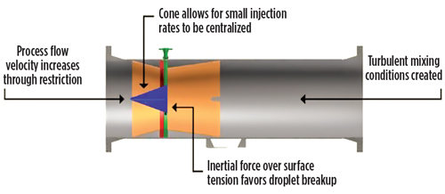 |
| Fig. 1. General design of the mixer.a |
The process involves the co-current injection of glycol to a compact simple inline mixer, in comparison to a counter-current tower (Fig. 2). The mixer has the same restrictions as a conventional tower and operates optimally under the same conditions as any dehydration unit.
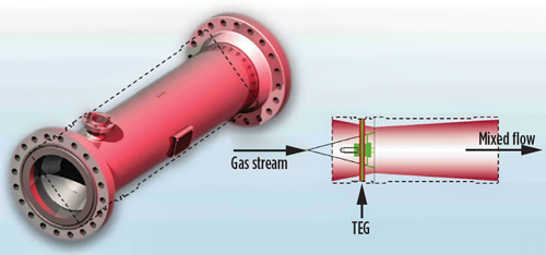 |
| Fig. 2. General operation of the mixer.a |
Case study with mixer implantation. The mixer was tested during dehydration of natural gas, using TEG, at a test facility in collaboration with a major operator. The test facility results were then compared to another company’s mixer model to identify the case study mixer’s dehydration performance via approach to equilibrium (ATE).
The testing showed that 100% ATE is achievable with the case study mixer. The results also proved that the mixer achieves the highest gas dehydration possible and can act as a single equilibrium stage in the natural gas dehydration processes.
The test results have implications for the development and use of compact dehydration systems on offshore platforms and at subsea wells, as well as for improving the performance and capability of existing dehydration systems that are underperforming.
Fig. 3 shows the setup of the test facility. The dry gas is compressed to the required pressure, circulated via a blower and then bubbled through water to saturate the gas. The gas stream enters the mixer, which increases the gas velocity due to a reduced open area. The saturated gas stream will contact the lean TEG as it is injected onto the surface of the inverted cone.
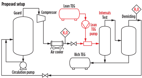 |
| Fig. 3. Flow diagram of natural gas dehydration setup. |
The testing team used lean and semi-lean TEG in separate tests to confirm the possibility of a two-stage compact system, with TEG flowing “counter-current” to the gas—i.e., lean TEG will enter the second mixer and treat the leaner and less-water-saturated natural gas.
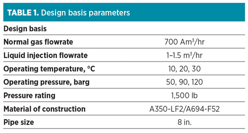
For analysis, the rich/semi-lean TEG from the separation vessels was then measured for water content using the Karl Fischer titration method. Gas samples were taken with gas chromatography to support measurements taken with laser meters. The basis of design for the testing is shown in Table 1.
 |
Approach to equilibrium and modeling. As a method to determine the performance of the mixer with regard to gas dehydration, the ATE for glycol absorption of water is determined. The ATE expresses the actual performance of the mixer (water vapor removal) in comparison to the theoretical equilibrium vapor, as shown in Eq. 1:
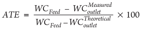 |
where:
WCFeed = Water content of saturated feed, ppm
= Water content of outlet dry gas (downstream of scrubber), ppm
= Theoretical water content of dry gas, ppm.
Previous work indicated that the mixer provides a reasonable level of expected natural gas dehydration, estimated to be 98% of the calculated ATE per the use of the Peng-Robinson Equation of State (PR-EOS). This requires consideration of a one-stage contactor with 100% removal of water per the incoming glycol purity and gas operating conditions.
From a simulation perspective, after the ATE is calculated, 2% of the removed water is added back to the main process flow to simulate a reasonable expectation for achievable gas dehydration.
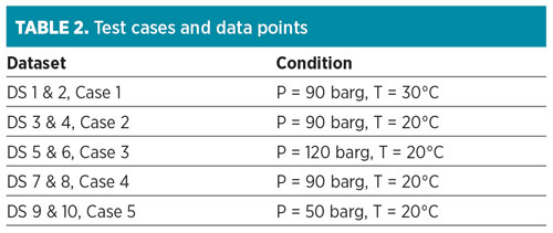
Test conditions and results. Five cases of test conditions were provided from testing partners, each with two sets of data points per condition. The respective cases and data points are shown in Table 2. More in-depth information about each data point was received, including flowrate, DP across the mixer, TEG flowrate, TEG purity, temperature and inlet water vapor content. These data (not provided here) were used to validate the mixer model.b
 |
Based on the data, the actual results can be compared to theoretical predictions used for the dehydration process, as well as validate the mechanical design of the mixer—i.e., pressure drop observed vs. the calculated value from the internal design spreadsheet. The data can also be used to confirm the existence, if any, of TEG losses.
When used for gas dehydration, the mixer is confirmed to create mixing conditions that efficiently use 98% of the estimated glycol capacity for water vapor absorption—i.e., the resulting ATE is 98%. In some cases, the resulting ATE was above 100%, with the lowest ATE observed just below 96%. Results above 100% ATE are possible, since it is known that the PR-EOS is a conservative EOS for simulation software. The PR-EOS often requires process designs with larger glycol flows, thus providing excess capacity should low performance be seen.
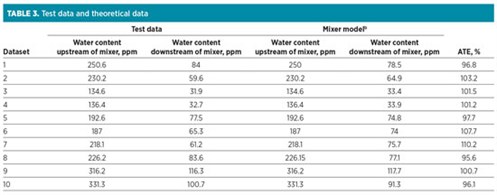
Table 3 shows the actual measured test results vs. the predicted mixer model results using PR-EOS. Fig. 4 represents how effectively the mixer performed, based on TEG dehydration ATE. The mixer was found to be equal to one stage of mass transfer (100% ATE), as compared to a 100% mixed stream of TEG and natural gas, or vs. an absorption column.
 |
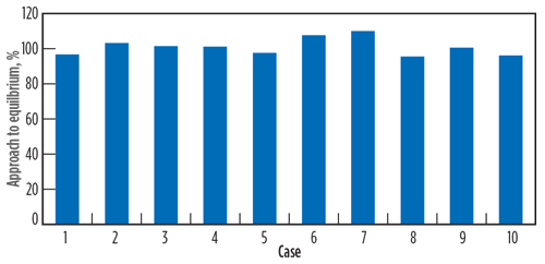 |
| Fig. 4. Dataset vs. ATE. |
In tests where the measured water content achieved an ATE above 100%, it can be said that the mixer has achieved a level of natural gas dehydration with TEG that is greater than one stage of mass transfer in the mixer model.b This is possible because, as aforementioned, it is widely accepted that the PR-EOS gives conservative estimates with regard to natural gas dehydration and required TEG circulation rates. A conservative approach is important so that offshore dehydration modules can be robustly designed with performance margins factored into consideration. When the ATE is below 100%, the level of dehydration achieved with the mixer and TEG injection is below the optimum level of water removal that can be theoretically achieved.
From the European measured test data, the ATE was reported to be at least 95% when using the mixer as one equilibrium stage in the dehydration process. In over half of the trials reviewed, a performance greater than one theoretical stage was observed.
Based on these test results, it can be concluded that the mixer is capable of achieving one equivalent equilibrium stage in the dehydration process and can achieve higher than one stage in some cases. Several key design parameters, such as Re number, momentum and DP can be used to provide a mechanically sound and high-performance, co-current mixing unit.
Momentum and performance. As with the fluids flow regime, behavior is important. It is also important to consider the momentum of the gas as it enters the throat of the mixer. The velocity increases at this point as the dynamic pressure decreases to the lowest point in the system.
Additionally, the performance of the mixer relies on the dimensionless Weber number, where droplet breakup occurs once inertial force exceeds liquid droplet surface tension. A graph of the lab results with ATE as a function of momentum at the throat is shown in Fig. 5.
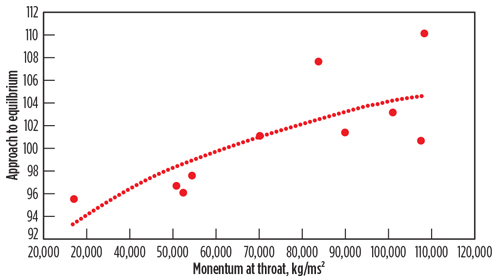 |
| Fig. 5. ATE vs. momentum. |
From the results shown in Fig. 5, it is recommended to target a momentum of approximately 60,000 kg/m.s2 to achieve maximum performance in the mixer. The momentum is important, alongside the Reynolds number consideration, as they consider the process conditions that would influence the density of the gas. This means it is important to consider the velocity and density of the gas at different conditions to maximize performance of the mixer for specific wellsite designs.
Takeaway. Using this case study as an example of how the mixer fits into the wider industry, the technology offers clients and operators an alternative for optimizing an existing system. It can allow existing processes to increase existing processing capacity or improve the outlet specifications (better end product) with minimum maintenance and disruption.
The FPSO application can mitigate poor performance of existing units to motion. The mixer also allows increase in capacity during mature field developments or extensions. It offers greater turndown than a contactor, reductions in CAPEX and OPEX, and less methanol injection, among other benefits. GP
Notes
a ProSep’s Enhanced Centre Located Injection Pipe Spool Element (ECLIPSE) mixer
b ProSep’s UniSim model for the ECLIPSE mixer
Eilidh Duncan is a Senior Process Engineer at ProSep.
Yuecun (Terry) Lou is a Senior Process Engineer at ProSep.
Greg Hallahan is the Director of Process Engineering and Product Development for ProSep.


Comments